

Introduction: Simple Remote Control for Arduino

There are a lot of Arduino projects that would benefit from a remote control. Here I walk through my successful attempt to set up wireless serial communication between two Arduinos. I'll break it down into more steps than probably necessary and try to point out some of the pitfalls I encountered along the way. Please comment if you have ideas on how to simplify or improve.
The end result of this project is a simple remote control that allows you to send both PWM and digital data from one Arduino to the other. It is a short step from this to using a joystick to control a robot, copter, boat, or car.
Step 1: Acquire Materials
2x Arduino Unos
2x xBee Radios (I used series 1, make sure yours are of the same type, series 1 won't work with series 2)
2x computers (I found it easier to keep things straight by using two different computers, you could do it with one.)
2x potentiometers
1x pushbutton
3x 330 Ohm resistors
1x 10k Ohm resistor
3x LEDs
2x Breadboards
many hook-up wires
Step 2: Build the Transmitter Circuit
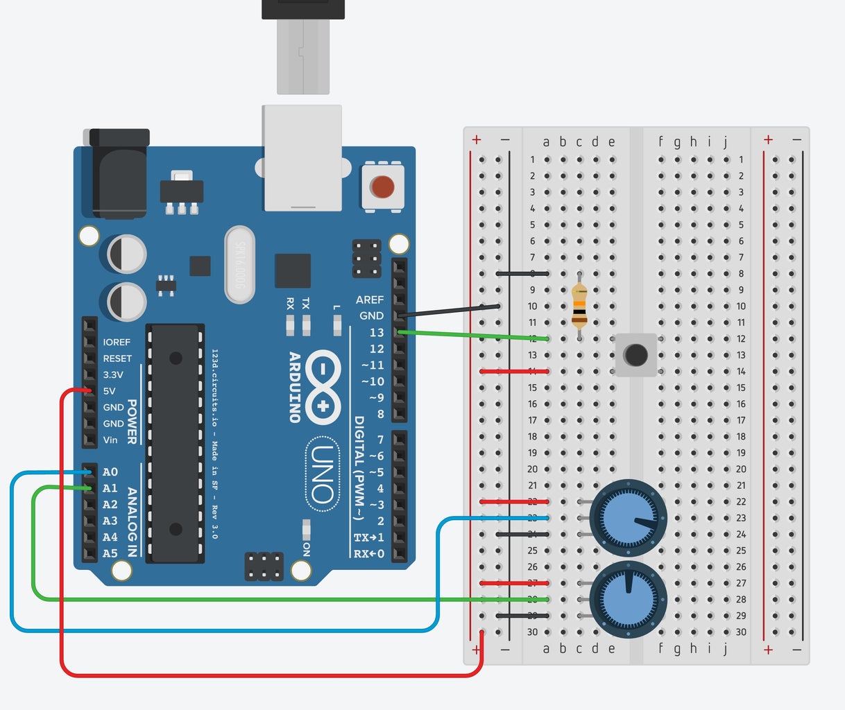
This Arduino contains two potentiometers and a pushbutton. In its place, you could use a joystick that has all three of these components built in, but as a basic first attempt, I kept them separate.
Make sure that your pushbutton resistor has a high value. I used 10K Ohms since that is Sparkfun's goto high resistor.
Step 3: Code the Transmitter's Arduino
Upload this code to the transmitter's Arduino Board. It is a very simple sketch that takes digital input from the button and analog input from the two potentiometers and produces a comma separated serial string:
vertOutput,horzOutput,selOutput
vertOutput ranges from 0 to 1023
horzOutput ranges from 0 to 1023
selOutput is either 0 (LOW) or 1 (HIGH)
Test this by opening the Serial Monitor in your Arduino IDE. Turn the knobs and push the button to make sure that it tracks. You should get a scroll of these strings down your monitor screen.
Note that I used a baud rate of 57600. Whatever rate you choose, you'll need to make sure that your xBee radios and Arduino Boards are all operating at the same rate.
/* Basic Joystick Program
output is string containing three comma separated values vertOutput,horzOutput,selOutput
*/
// Set up pins for joystick input
int selPin = 13;
int vertPin = A0;
int horzPin = A1;
boolean selOutput;
int vertOutput;
int horzOutput;
int ledPin = 13; // Set up output pin for testing the button
void setup() {
// input pins for joystick, output pin to test button
pinMode(ledPin, OUTPUT);
pinMode(selPin, INPUT);
pinMode(vertPin, INPUT);
pinMode(horzPin, INPUT);
Serial.begin(19200);
}
void loop() {
vertOutput = analogRead(vertPin);
horzOutput = analogRead(horzPin);
selOutput = digitalRead(selPin);
Serial.print(vertOutput);
Serial.print(",");
Serial.print(horzOutput);
Serial.print(",");
Serial.println(selOutput);
}
Attachments

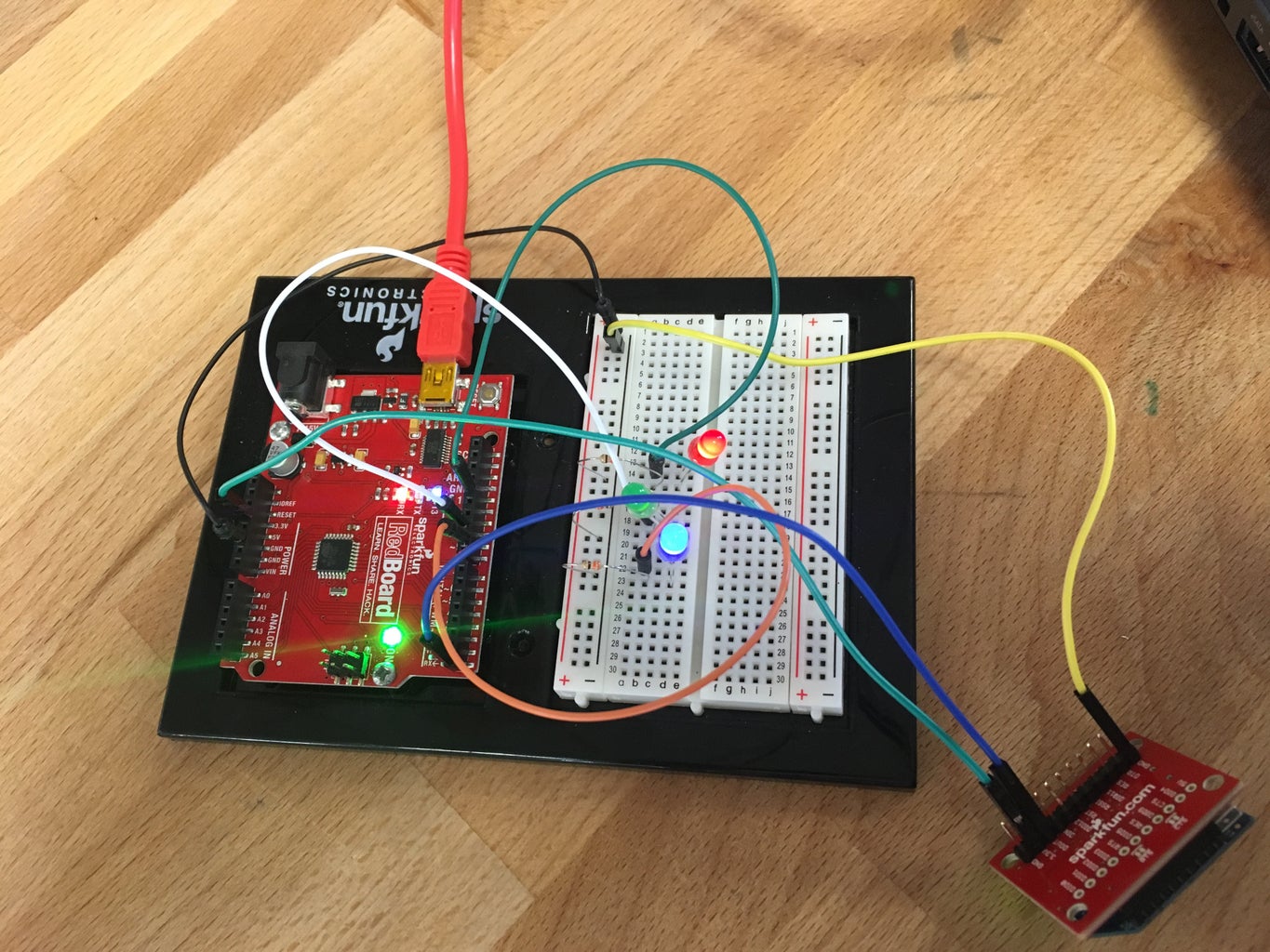
Step 4: Build the Receiver Arduino Circuit
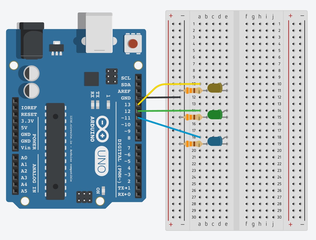
This is a proxy for your robot, car, quad, etc. The basic circuit contains three LED's two that dim from the potentiometer controls and one that either on or off via the button. The resistors for these LED's should be a lower value. 330 Ohms is a good choice.
Step 5: Program Receiver Arduino
The attached code allows you to control the receiver with serial communication. Upload the code and then open the serial monitor.
Here is a discussion of the code:
String vertPot;
String horzPot;
String buttonPot;
int vertVal;
int horzVal;
int buttonVal;
int vertPin = 11;
int horzPin = 12;
int buttonPin = 13;
String myString = "255,255,1";
String list[3];
This block establishes the variables used in the sketch. Most notably, we create an array of strings called list that contains three members. We'll parse the incoming data stream into those elements.
Here is the setup function:
void setup() {
pinMode(vertPin, OUTPUT); // set up the three output pins
pinMode(horzPin, OUTPUT); //
pinMode(buttonPin, OUTPUT); //
Serial.begin(19200); // Start serial communication, make sure you use a consistent baud rate
while (!Serial) {
;
// wait for serial port to connect. Needed for native USB
}
}
Here is the main loop:
void loop() {
if(Serial.available() > 0) {
myString = Serial.readStringUntil('\n'); // Read incoming date into a string until the line feed
}
String horzPot = getValue(myString,',',0); // Store the first value of the incoming string
String vertPot = getValue(myString,',',1); // Store the second value of the incoming string
String buttonPot = getValue(myString,',',2); // Store the third value of the incoming string
Serial.print(horzPot); // Serial print the values again, useful for debugging, but not necessary.
Serial.print(",");
Serial.print(vertPot);
Serial.print(",");
Serial.println(buttonVal);
horzVal = map(horzPot.toInt(),0,1023,0,255); // map the analog inputs (0-1023) to analog output (0-255)
vertVal = map(vertPot.toInt(),0,1023,0,255);
buttonVal = buttonPot.toInt();
analogWrite(vertPin, horzVal); // use incoming values to turn on the lights
analogWrite(horzPin, vertVal);
digitalWrite(buttonPin, buttonVal);
}
Here is the function, getValue, borrowed from this stackoverflow thread:
// http://stackoverflow.com/questions/9072320/split-...
It helps to split myString which consists of three comma separated values into an array with three members:
String getValue(String data, char separator, int index)
{
int found = 0;
int strIndex[] = {0, -1};
int maxIndex = data.length()-1;
for(int i=0; i<=maxIndex && found<=index; i++){
if(data.charAt(i)==separator || i==maxIndex){
found++;
strIndex[0] = strIndex[1]+1;
strIndex[1] = (i == maxIndex) ? i+1 : i;
}
}
return found>index ? data.substring(strIndex[0], strIndex[1]) : "";
}
Attachments
Step 6: Test WIRED Communication Between Your Two Boards
Before you mess with the radios, make sure that your boards are sending and receiving what you think they are. This way, if things don't work once you've added the radios, you'll know that the problem is with the radios, and not your code or existing circuits.
Run a wire from pin 1 (TX) on your transmitter to Pin 0 (RX) on the receiver. Also, run a wire to connect ground on your receiver to ground on your transmitter. I didn't do this at first and couldn't figure out why it didn't work!
With both Arduinos connected and powered, you should see the results of your knob turning and button pressing on both of the serial monitor screens and on the receiver LED's as in the video. If this works, you are ready for Wireless!
NOTE: Whenever you have wires attached to TX or RX pins, you will potentially disrupt your ability to upload code to your board. Make sure to disconnect these wires if you need to re-upload!
Step 7: Program Your XBee Radios
There are many sources for information on how to configure your xBee radios. Here is the one that I used from Sparkfun. I also used the xBee explorer to connect the radios to my Mac.
https://learn.sparkfun.com/tutorials/exploring-xbe...
Some key things to remember:
- Make sure that both radios have the same PAN ID (you choose this yourself) and baud rate. 57600 was the fastest one that I could get to work. Make sure this is the same rate both of your Arduinos are running.
- Make sure that the DL on one radio is the same as the MY on the other (and vice-versa) This will allow them to talk to each other.
- Examples: Radio A (PAN ID=3332, DH=0, DL=1, MY=0) / Radio B (PAN ID=3332, DH=0, DL=0, MY=1)
Once you have configured your radios, it is time the connect them and make your system wireless.
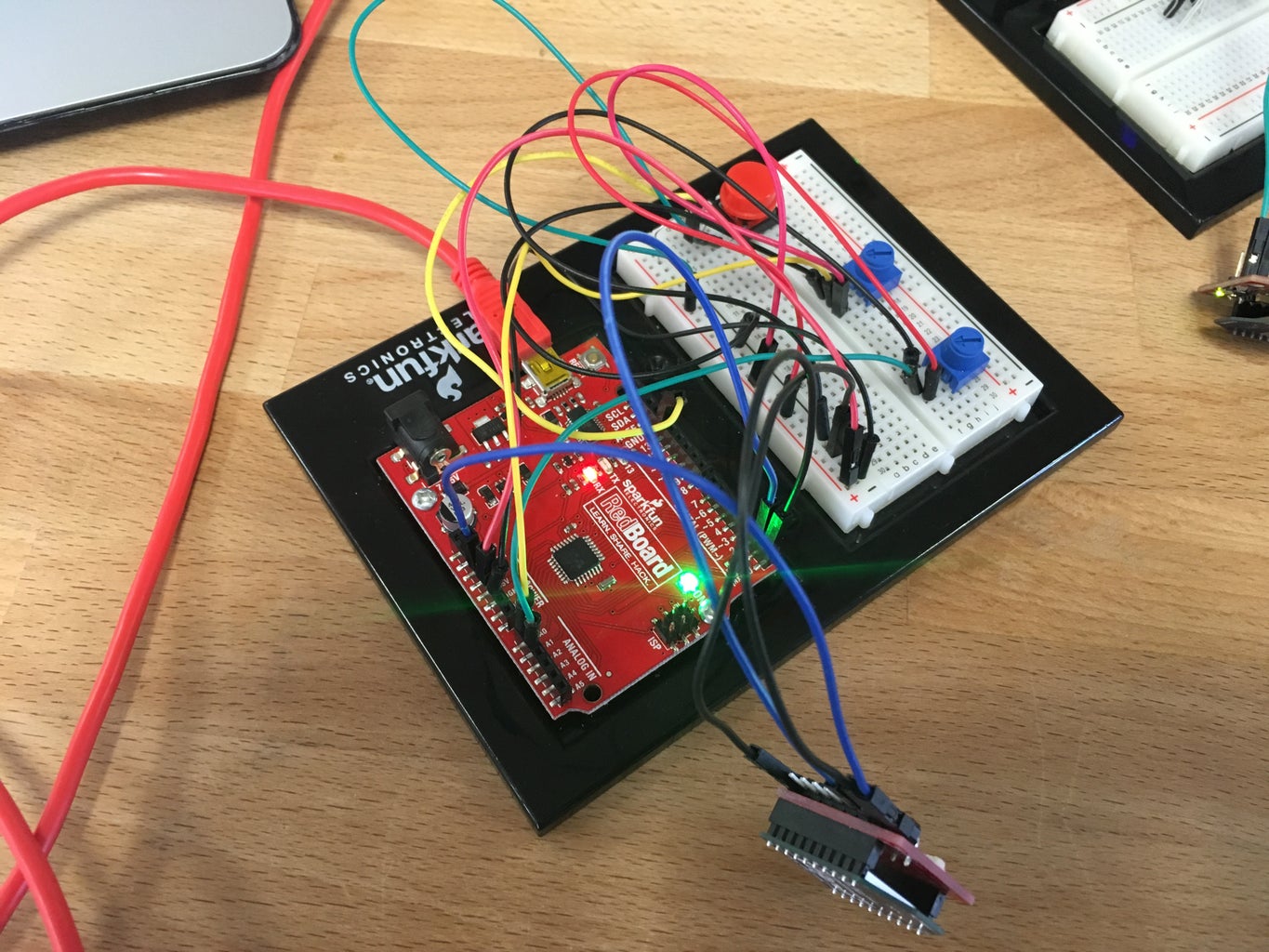
Step 8: Attach XBees to Transmitter and Receiver
Mount your xBees into xBee breakout boards.
Disconnect the wires (Ground and TX--> RX) that you used to test wired communication.
On the transmitter: attach from the breakout board to your Arduino:
- VCC --> 3.3 V
- GND --> GND
- Din --> TX (This was counter-intuitive to me)
On the receiver:
- VCC --> 3.3 V
- GND --> GND
- Dout --> RX
You should now have the same behavior as the wired version if everything is configured properly.
Step 9: Test Your Setup and Plan Wireless World Domination.
Turn the knobs and push the button to see if your remote control works. If not, look through the notes I have added that point out problems that I encountered or post to comments.
If so, see what you can do to make it your own.
Modify the transmitter string and hardware for more inputs, joysticks, buttons, etc.
Modify the receiver to control motors, servos, lights, etc.
If you found a mistake or inefficiency in my approach, please let me know.
Good luck!
