

Introduction: Simulating a Relay Activated Lamp in TinkerCAD


We will be using some components and some code to simulate a light bulb turning on automatically when it becomes dark, and turning off when it becomes bright.
Supplies
You will need:
- A resistor (1k ohms)
- A breadboard
- A light bulb
- A photo-resistor
- A power supply
- A relay
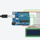
Step 1: Setting Up the Circuit


The first thing you want to do is to connect 5V power and ground from the Arduino to the positive and negative rails on a breadboard respectively. These are marked red for positive, black for negative.
Then, you will hook up the photo-resistor and resistor. We are going to have the photo-resistor be connected to the A0 pin, an analog pin. This is because the photo-resistor takes an analog measure of the light level surrounding it.
Next is the relay and power supply. The Arduino only supplies 5v of power itself, so we will need the relay to provide the 120V that the light bulb needs. We will connect terminal 1 of the relay to the negative on the power supply, terminal 8 to ground and terminal 5 to digital pin 4.
Lastly, the light bulb. One end of the light bulb will go into the positive side of the power supply, and the other end will go into terminal 7 of the relay.
Step 2: The Code
The code should look something like this:
void setup()
{
  pinMode(A0, INPUT);
  Serial.begin(9600);
  pinMode(4, OUTPUT);
}

void loop()
{
  Serial.println(analogRead(A0));
  if (analogRead(A0) > 500) {
    digitalWrite(4, LOW);
  }
  else {
    digitalWrite(4, HIGH);
  }
}
This initializes the inputs and outputs as well as the serial connection. In this case, the analog pin A0 is an input and the digital pin 4 is an output. The serial connection is set to 9600 bits per second, the default amount of data the Arduino sends.
void setup()
{
   pinMode(A0, INPUT);
   Serial.begin(9600);
   pinMode(4, OUTPUT);
}
This code is how we are going to make the light bulb turn on or off based on the lighting conditions. Firstly, we print the data that pin A0 is getting, which in this case would coming from the photoresistor, based off the lighting condition. Then we make it so that when this number we are reading is above 500, we write pin 4 to be low. Pin 4 is connected to our relay, and when we write a low to it, we are giving it no current, which means that there isn't enough current to activate the larger current. Otherwise, we write a high, which allows the light bulb to turn on.
<pre data-children-count="0" style="font-size: 13.5px;">void loop()
{
   Serial.println(analogRead(A0));
   if (analogRead(A0) > 500) {
      digitalWrite(4, LOW);
   }
   else {
     digitalWrite(4, HIGH);
   }
}
Step 3: The Results
Simulating this circuit in TinkerCAD, we can see that as the light bulb turns on as we start the simulation. As we adjust the light level that the photoresistor is reading to be brighter, the lightbulb eventually turns off.


