

Introduction: Smart Home Systems With Arduino


Definition:
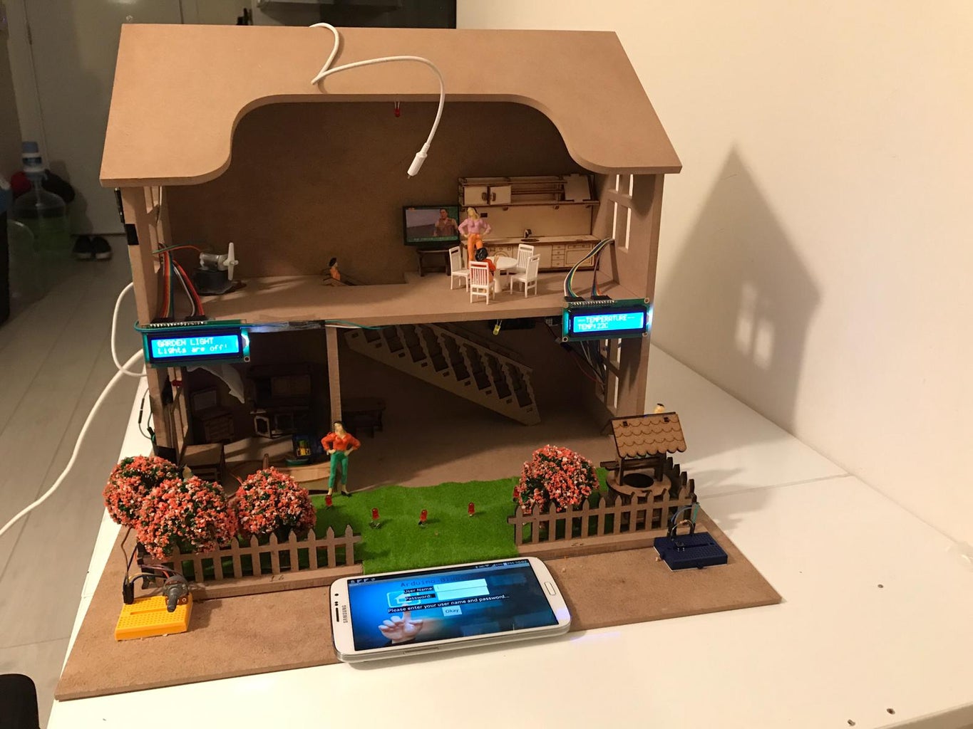
Seven different systems used in Smart Home Systems with Arduino project are designed to make people's lives easier by communicating with each other without the need for manpower. This intelligent system, created by a combination of door system, curtain system, home lighting system, garden lighting system, temperature system, solar power system and fan system, is managed by a microcontroller and Android phone. The door system is controlled by voice command using the Android phone and directs the motor used in the door lock according to the instructions that allow the door to open and close. The curtain system works in the same way as the door system. It is controlled by voice command using the Android phone and directs the motor used in the screen movement according to the instructions allowing the curtains to be opened and closed. Home Lighting system and fan system are controlled by telephone. The temperature sensor in the temperature system controls the internal temperature of the house and allows the fan to operate. It also prints data on the LCD screen. Garden lighting system is controlled by potentiometer. There are three modes in total. These inter-mode transitions are performed using a potentiometer. In another system the phone is charged with solar energy.
Step 1: Garden Lighting System

Working principle of the system:
There are 3 different mode options in the garden lighting system.
Inter-mode transitions are performed using a potentiometer. The first mode allows the lights to turn off completely. The second mode works by falling below the light level determined by the code depending on the Light Dependent Resistor(LDR), and the light increases or decreases depending on the intensity of light coming to the Light Dependent Resistor(LDR). The third mode allows the lights to remain on completely. It also displays the mode transitions on the LCD screen.
1-First mode --> potDeger >= 1020//Potentiometer value
2-Second mode --> potDeger <= 1000 && potDeger >= 65)//Potentiometer value
3-Third mode --> potDeger <= 20//Potentiometer value
Arduino Code:
- #include
- const int rs = 12, en = 11, d4 = 5, d5 = 4, d6 = 3, d7 = 2;
- LiquidCrystal lcd(rs, en, d4, d5, d6, d7);
- int led = 10;
- int butonPin = 6;//Button pin value
- int potPin = A0;//Potentiometer pin value
- int ldrPin = A1;//light dependent resistor(LDR) pin value
- void setup()
- {
- pinMode(led, OUTPUT);
- pinMode(6, INPUT);
- lcd.begin(16, 2);
- lcd.print("GARDEN LIGHT");
- Serial.begin(9600);
- }
- void loop()
- {
- int butonDeger = digitalRead(butonPin);//Button value
- int potDeger = analogRead(potPin);//Potentiometer value
- int ldrDeger = analogRead(ldrPin);//Light dependent resistor(LDR) value
- int LedParlaklikDegeri = map(ldrDeger, 0, 255, 0, 255 );//Led brightness value
- delay(50);
- Serial.println(potDeger);
- //lcd.setCursor(0, 1);
- if (potDeger >= 1020)
- {
- lcd.setCursor(0, 1);
- lcd.print("Lights are on!");
- digitalWrite(led, HIGH);
- }
- else if (potDeger <= 20)
- {
- lcd.setCursor(0, 1);
- lcd.print("Lights are off!");
- digitalWrite(led, LOW); }
- if (potDeger <= 1000 && potDeger >= 65)
- {
- lcd.setCursor(0, 1);
- lcd.println("Sensor Active! ");
- if (ldrDeger <= 20) { digitalWrite(led, HIGH);
- }
- else if (ldrDeger >= 21 && ldrDeger <= 26)
- {
- analogWrite(led, 75);
- }
- else if (ldrDeger >= 27 && ldrDeger <= 35)
- {
- analogWrite(led, 50);
- } else if (ldrDeger >= 36 && ldrDeger <= 41)
- {
- analogWrite(led, 25);
- } else if (ldrDeger >= 42 && ldrDeger <= 47)
- {
- analogWrite(led, 5);
- }
- else if(ldrDeger >=48)
- {
- analogWrite(led, 0);
- }
- }
Step 2: Fan Control System With Temperature Sensor

Working principle of the system:
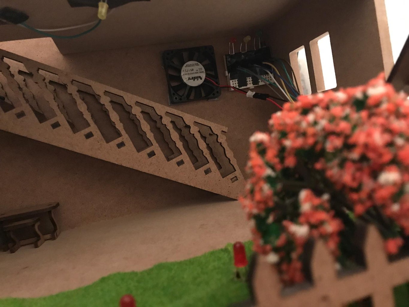
Data from temperature sensor(LM35) is read in Arduino. Fan control is provided by the temperature value determined by the code. For example, fan operation is provided when the temperature exceeds 26C. The most important point of this system is that it has 3 modes. The button switches between modes. What are modes?
1.Mode: Keep fan control on continuously.
2.Mode: Operation of the fan connected to the temperature sensor(LM35).
3.Mode: Keeping the fan control fully closed.
There are three LEDs which indicate which mode it is.
1.Mode: The red LED is lit in mode.
2.Mode: In the mode yellow led is lit.
3.Mode: Green LED is lit in mode.
Important components of the system:
Temperature sensor(LM35).
NPN transistor(BD139).
Arduino Code:
- int tempPin = A0;
- int fan = 11;
- int led = 8;
- int temp;
- int tempMin = 27;
- int tempMax = 70;
- int buton = 6;
- int led1 = 7;
- int led2 = 4;
- int led3 = 5;
- void setup()
- {
- Serial.begin(9600);
- pinMode(fan, OUTPUT);
- pinMode(led1, OUTPUT);
- pinMode(led2, OUTPUT);
- pinMode(led3, OUTPUT);
- pinMode(tempPin, INPUT);
- pinMode(buton, INPUT);
- }
- void loop()
- {
- temp = readTemp();
- int butonDeger = digitalRead(buton);
- Serial.println(temp);
- while (butonDeger)
- {
- if (digitalRead(buton) == HIGH)
- {
- if (butonDeger == 1)
- {
- for (int i = 0; i < 3; i++)
- {
- digitalWrite(led1, HIGH);
- digitalWrite(led2, HIGH);
- digitalWrite(led3, HIGH);
- delay(200);
- digitalWrite(led1, LOW);
- digitalWrite(led2, LOW);
- digitalWrite(led3, LOW);
- delay(200);
- }
- }
- butonDeger++;
- }
- if (butonDeger == 5)
- {
- butonDeger = 2;
- }
- delay(200);
- switch (butonDeger)
- {
- case 2:
- digitalWrite(fan, HIGH);
- digitalWrite(led1, HIGH);
- digitalWrite(led2, LOW);
- digitalWrite(led3, LOW);
- break;
- case 3:
- digitalWrite(fan, LOW);
- digitalWrite(led1, LOW);
- digitalWrite(led2, HIGH);
- digitalWrite(led3, LOW);
- break;
- case 4:
- temp = readTemp();
- Serial.println(temp);
- digitalWrite(led1, LOW);
- digitalWrite(led2, LOW);
- digitalWrite(led3, HIGH);
- if (temp > tempMin)
- {
- digitalWrite(fan, HIGH);
- }
- else if (temp < tempMin)
- {
- digitalWrite(fan, LOW);
- }
- break;
- default:
- break;
- }
- }
- delay(200);
- }
Step 3: Temperature System With Two Arduino

Working principle of the system:
Firstly, The most important circuit elements used in the system: Two Arduino and two NRF24L01 wireless module. You have noticed that this system has 2 Arduino. Why so? The most important point in making the temperature system in this project is the exchange of data between two Arduino wireless connections. One is the Arduino receiver and the other is the transmitter. Which is the recipient of the data to decide which of the coding is decided. Transmitter The value is read by the temperature sensor(LM35) in the Arduino and the receiver prints the value from the Arduino on the LCD screen. This way you can send the data you want.
Components of the system:
Arduino
NRF24L01 wireless module
Temperature sensor(LM35)
16x2 LCD
10K Potentiometer
Arduino Code:
1-Transmitter Code:
- #include
- #include "RF24.h"
- const int analogPin = A0;
- float gerilimDeger = 0;
- float sensorDeger = 0;
- float sicaklikDeger = 0;
- int pot = A1;
- int fan = 6;
- int tempMax = 27;
- int msg[1];
- //SCK -> 13
- //MISO -> 12
- //MOSI -> 11
- //CSN -> 7
- //CE -> 8
- RF24 radio(8, 7);
- const uint64_t pipe = 0xE8E8F0F0E1LL;
- void setup(void)
- {
- Serial.begin(9600);
- pinMode(fan, OUTPUT);
- radio.begin();
- radio.openWritingPipe(pipe);
- }
- void loop(void)
- {
- sensorDeger = analogRead(analogPin);
- gerilimDeger = (sensorDeger / 1023) * 5000;
- sicaklikDeger = gerilimDeger / 10.0;
- msg[0] = sicaklikDeger; radio.write(msg, 1);
- }
- }
2- Receiver Code:
- #include
- #include
- #include "RF24.h"
- const int rs = 9, en = 6, d4 = 5, d5 = 4, d6 = 3, d7 = 2;
- LiquidCrystal lcd(rs, en, d4, d5, d6, d7);
- //SCK -> 13
- //MISO -> 12
- //MOSI -> 11
- //CSN -> 7
- //CE -> 8
- RF24 radio(8, 7);
- const uint64_t pipe = 0xE8E8F0F0E1LL;
- int msg[1];
- void setup()
- {
- Serial.begin(9600);
- lcd.begin(16, 2);
- lcd.print("--TEMPERATURE--");
- delay(1000);
- radio.begin();
- radio.openReadingPipe(1, pipe);
- radio.startListening();
- }
- void loop()
- {
- if (radio.available())
- {
- bool done = false;
- while (!done)
- {
- done = radio.read(msg, 1);
- lcd.setCursor(0, 1);
- lcd.print("TEMP: ");
- lcd.setCursor(7, 1);
- lcd.print("C");
- lcd.setCursor(5, 1);
- lcd.print(msg[0]);
- }
- delay(5000);
- }
- }
Step 4: Android Phone Controlled Systems
Working principle of the systems:
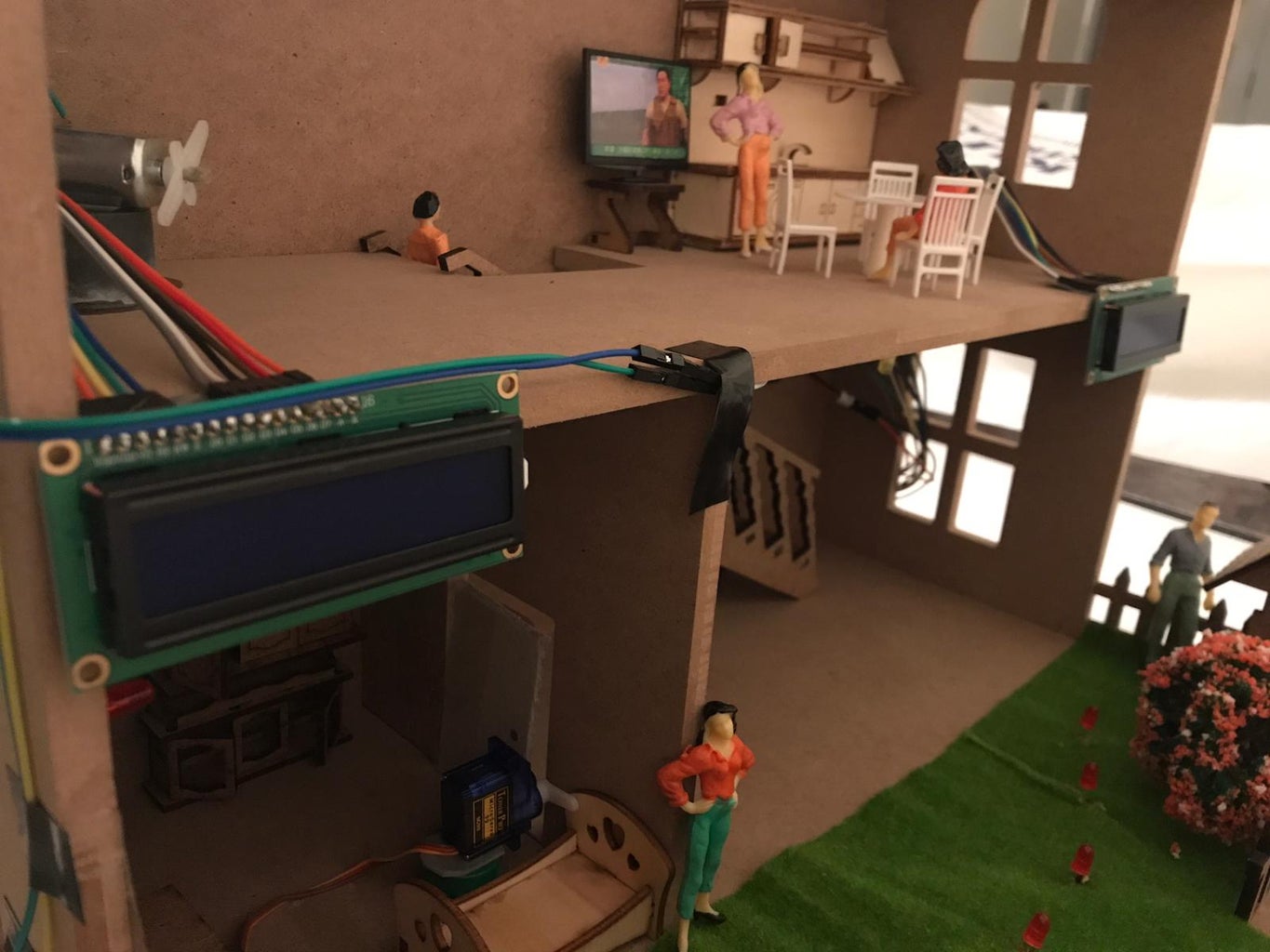
Systems that use HC-06 module are used to make a bluetooth connection with an Android data-based phone (tablet, etc.). After the connection is made, an Android application (App Inventor-2 (MIT),etc.) can be used with the help of the developer to perform certain encodings, for example by controlling the motor control, light switching on and off. -In this project, the light system, fan system, door open and close by the voice command and the curtain is opened and closed by the voice command can be controlled by Android phone connection. After the entry is done correctly, the control screen of four systems (lighting system, fan system, door system, curtain system) is opened. There are separate buttons for each system. After logging in to a desired system, it requires a bluetooth connection and a connection must be made for each system. The most important thing is that the systems do not close when you exit the application. After re-entry, systems can be controlled from where they were left.
1.Lighting System:
The prototype house in the Smart Home System project has 3 rooms in total. Each room has its own lighting and is controlled by the Android phone. There are two buttons for each room: "Açık" and "Kapalı".
2.Fan System:
This system is also controlled in the same way with Android phone. A total of 3 steps are set and a "STOP" button is available.
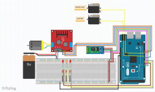
Componenets: DC Motor and L298N Motor Driver
3.Door-Lock System:
There are two command-detector words in the system controlled by voice command. (The words "open" and "closed" are the Turkish words. if you want to english language, you can define the code.)(You just write "Open" where you see "Açık"(Arduino IDE). In the same way, you just write "Close" where you see "Kapalı"(Arduino IDE)). -Door lock system is provided with Mini Servo motor.
4.Curtain System:
There are two command-detector words in the system controlled by voice command. (The words "Perde açılsın" and "Perde kapansın" are the Turkish words. if you want to english language, you can define the code.)(You just write "Curtain open" where you see "Perde açılsın"(Arduino IDE).In the same way, you just write "Curtain close" where you see "Perde kapansın"(Arduino IDE)).
Arduino Code:
- #include
- Servo servoMotor;
- Servo servoMotor2;
- String state;
- int led = 8;
- int led4 = 5;
- int data;
- int led1 = 2;
- int led2 = 3;
- int led3 = 4;
- int in1 = 10;
- int in2 = 11;
- int enA = 6;
- int motorStop = 0;
- int speed1 = 75;
- int speed2 = 125;
- int speed3 = 255;
- int leddurum = 0;
- boolean motordurum = 0;
- void setup()
- {
- pinMode(led1, OUTPUT);
- pinMode(led2, OUTPUT);
- pinMode(led3, OUTPUT);
- pinMode(in1, OUTPUT);
- pinMode(in2, OUTPUT);
- pinMode(enA, OUTPUT);
- pinMode(led, OUTPUT);
- pinMode(led4, OUTPUT);
- servoMotor.attach(9);
- servoMotor2.attach(7);
- Serial.begin(9600);
- }
- void loop()
- {
- while (Serial.available())
- {
- delay(10);
- int data = Serial.read();
- char deger = char(data);
- state += deger;
- //delay(100);
- if (data == '1')
- {
- digitalWrite(led1, HIGH);
- delay(500);
- }
- else if (data == '0')
- {
- digitalWrite(led1, LOW);
- delay(500);
- data = data + 2;
- }
- else if (data == '2')
- {
- digitalWrite(led2, HIGH);
- delay(500);
- data = data + 1;
- }
- else if (data == '3')
- {
- digitalWrite(led2, LOW);
- delay(500);
- data = data + 1;
- }
- else if (data == '4')
- {
- digitalWrite(led3, HIGH);
- delay(500);
- data = data + 1;
- }
- else if (data == '5')
- {
- digitalWrite(led3, LOW);
- delay(500);
- data = data + 1;
- }
- else if (data == '6')
- {
- analogWrite(enA, speed1);
- digitalWrite(in1, HIGH);
- digitalWrite(in2, LOW);
- data = data + 1;
- }
- else if (data == '7')
- {
- analogWrite(enA, speed2);
- digitalWrite(in1, HIGH);
- digitalWrite(in2, LOW);
- data = data + 1;
- }
- else if (data == '8')
- {
- analogWrite(enA, speed3);
- digitalWrite(in1, HIGH);
- digitalWrite(in2, LOW);
- data = data + 1;
- }
- else if (data == '9')
- {
- analogWrite(enA, motorStop);
- digitalWrite(in1, LOW);
- digitalWrite(in2, LOW);
- data = data + 1;
- }
- }
- if (state == "açık")
- {
- digitalWrite(led, HIGH);
- digitalWrite(led4, LOW);
- servoMotor.write(90);
- }
- else if (state == "kapalı")
- {
- digitalWrite(led, LOW);
- digitalWrite(led4, HIGH);
- servoMotor.write(10);
- }
- else if (state == "perde açılsın")
- {
- servoMotor2.write(350);
- }
- else if (state == "perde kapansın")
- {
- servoMotor2.write(10);
- }
- state = "";
- }
Step 5: App Inventor for Android Phone


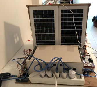
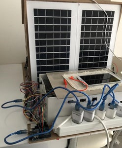
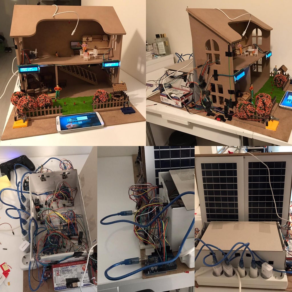
Step 6: Battery Charge With Solar Energy

The voltage value is doubled by connecting two 6v 15w solar panels in series. Following the specific cable connections using the TP4056 type module, connection to the 18650 type 3.7v li-ion battery was made. A fixed 5v 1a value usb circuit board was used as output.


