

Introduction: Smart Lock Using Arduino and Deadbolt

- The purpose of our project is to create an alternative way for someone to lock and unlock their door without having to keep track of keys.
- It provides an easier way to control a lock and reduces the risk of getting locked out.
- Intuitive Lock enables a keyless entry to any house/apartment that uses a deadbolt lock, making it much more convenient.
Step 1: List of Materials


1. Arduino
-Use for compatibility with the servo. Allows for a certain sequence of the motor (as seen in the code)
2. A high torque servo motor
-Replaces the spring in the deadlock that moves it in and out.
3. Wood for enclosure
-Can make the enclosure out of any material
4. A deadbolt lock
-Can buy a new one or replace the one in current door
5. Breadboard(optional)
-Can solder wires instead to save space
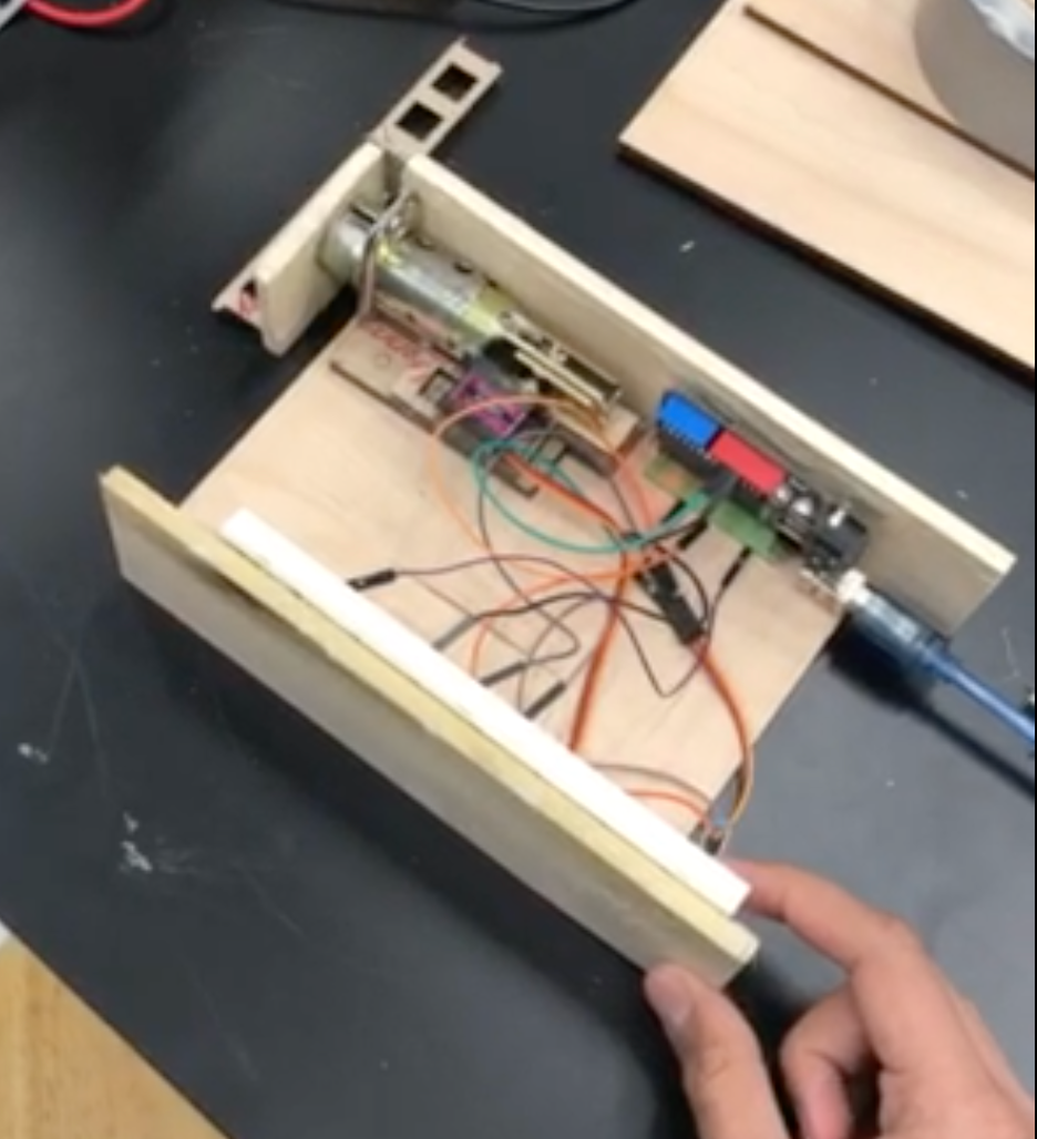
Step 2: Building the Enclosure


The design requires an enclosure for the breadboard, the switch and the Arduino. The goal was to make it look neat and for the wiring to be covered. For this we made a box with plywood which was covered on the top, bottom, and left open on the sides. We wanted to enclose the unit in order to protect the wires and Arduino from potentially breaking if it were to get hit or fall.
For this part of the project, any kind of enclosure would work so long as its compact yet effective for its purpose.
Step 3: Setting Up the Electronics


Servo-controlled deadbolt mechanism:
One of the most difficult issues we faced when assembling our final project was assembling a remote device that had enough power to push a deadbolt by itself.
In order to overcome this obstacle, we found our original servo was too weak to move our deadbolt mechanism by itself. In order to meet the new torque requirements, we had to sacrifice the wireless capabilities of a nodeMCU and use an Arduino (which runs on language C++).
Lack of power of the stepper forced us to find another solution in order to power our mechanism. To do this, we completely took apart the deadbolt mechanism and removed the spring that put resistance on the deadbolt. After this we removed the manually moveable arm inside the deadbolt, which we recognized was the same size as the servo arm. After some adjustments to the deadbolt, we reassembled it with a new (moveable arm) which was a servo. We were finally able to program the Arduino to, at the press of a button, move the servo arm from the left (locked) to the right (unlocked). Once the button is released, the servo arm moves the deadbolt back to the locked position.
Step 4: Develop the Code

1. The constant lines of this code tell the Arduino which pins to read when evaluating the code
2. If the button is being pushed, the Arduino recognizes (reads) and then tells the servo to move 175 degrees on its axis to the left. The deadbolt housing restricts the servo’s range of motion, however, the deadbolt itself recedes and unlocks completely, just as it would if it were manually moved
3. Once the button is released, the Arduino reads this and tell the servo to return to its locked position, completing the process of reading the code.
Step 5: Demo
A short video will demonstrate the servo deadbolt mechanism in action

