

Introduction: Smart Thermometer


The smart thermometer is an Arduino thermometer that not only displays the exact current temperature with an LCD but also gives you visual feedback at a glance using a string of three Adafruit NeoPixels. When the temp is within 65-75 degrees the lights are green, if it is bellow the lights turn blue, and if it is above they turn red. I made this as a tutorial to teach other students at my school Riverpoint Academy, how to use for loops and arrays.
Step 1: Materials and Tools
Materials
-Arduino Uno http://www.adafruit.com/products/50
-Temp Sensor http://www.adafruit.com/products/165
-Jumper Wires http://www.adafruit.com/products/1957
-LCD Display http://www.adafruit.com/products/181
-Potentiometer http://www.adafruit.com/products/356
-Bread Board http://www.adafruit.com/products/64
-Neopixels http://www.adafruit.com/products/1260
Optional Materials
-Wood or acrylic plastic (only if you want to make an enclosure for the project)
-Wood glue or two part epoxy
-Half Sized Breadboard PCB http://www.adafruit.com/products/1609
Tools
-Computer
-Your Hands
-Soldering Iron (Optional)
Step 2: Connecting Your Temp Sensor


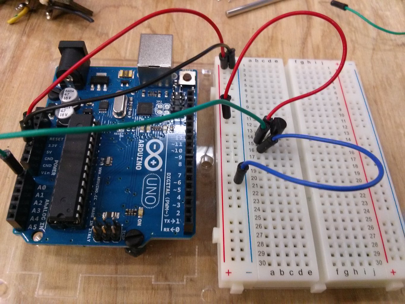
Start by connecting your 5v and ground. Follow the picture on the bottom left. It will allow you connect all of the other components that also need 5v. Now connect your temperature sensor. Here is the basic pinout that you will need. Far left pin to 5v, middle pin to analog 0 on the Arduino and far right to ground. Also if you are new to using a bread board, here is a link to a breadboard tutorial: https://learn.sparkfun.com/tutorials/how-to-use-a-breadboard
Step 3: Connecting Your LCD


Connect your LCD display and potentiometer. Follow this schematic exactly. The extra 5v and ground connections are only necessary if you want your lcd to have a backlight.
Step 4: Attaching Your Neopixel Strip


Attach your strip of NeoPixels to the Arduino. Green wire(the data wire) goes to pin 6, red wire goes to 5v and black goes to ground. Here is a great resource if you want to know more about how NeoPixels work: https://learn.adafruit.com/adafruit-neopixel-uberguide/overview
Step 5: Importing Necessary Librarys

Now that you have your basic code you will need to import your needed libraries. Libraries are basically extensions that allow you to do things that you normally could not do with the Arduino. You will need to import the Liquid Crystal Library which is already on your computer. Also you will need to download the NeoPixel library from Adafruit if you don't already have it on your computer. You can do that here:
Step 6: Code Part 1
Arrays
In the setup code you create all of your variables and arrays. An array is a collection of variables that can be called on later in the program. In this program “values” is an array with 5 different variables. Arrays always count from zero,so the first value in a array is index 0 then index 1 and so on. Index is the location of the variable in the array. You can get the setup code here:
https://github.com/AidanMaddox/Temp/blob/master/Setup%20Code
Array Examples:
values[5]; //this means values, is an array that can store 5 values
values[] = {1,2,3}; //this means values, is an array that holds the values 1,2 and 3
Step 7: Code Part 2
Void Loop and For Loop
With a void loop it runs through the code and then starts over voiding what previously happened and doing it all over again. Everything inside the void loop code will run indefinitely until it is told to stop. In this section of code we use for loops to run a specific section of code a select number of times. Below is an example of a for loop. In a for loop you first create a variable in this case i and set its value. Then you set a constraint that says run until this is no longer true. In this case as long as i < 5 the for loop will run. Then you tell the value i to add one every time the for loop runs by saying i++. So with this for loop, it will run 5 times before it resets. You can get the loop code here:
https://github.com/AidanMaddox/Temp/blob/master/V...
For Loop Example:
for(int i = 0; i<5; i++){
//your code here
}
Step 8: Creating the Box (optional)
For this step you will need a laser cutter and the DXF files below. It should be fairly straightforward to assemble the box so, Im going to leave the assembly up to you. This is were you will need the PCB, because it is smaller than a actual bread board. If you want you could even use a proto-shield, but I did not have one. Solder all of the connections just like they were connected on the bread board and you should be set. I ended up drilling a hole in the side for the nine volt power supply. Also feel free to create your own box design; if you do I would suggest going a little bigger. Mine only has hinges so that people could see how it works.
Attachments

Step 9: Finishing/Trouble Shooting


Now that you have all the code, the only thing left is to plug in your Arduino and upload the code. If you have done everything right, the lcd should light up and begin displaying the current temp. If it doesn't then the most likely reason is that some of your jumper wires are improperly connected. Go back to steps 1 through 3 and check to make sure everything is connected right. If you get a code error, it is probably due to installing the neo pixel library incorrectly. Go back to step 4 and walk through the library instal guide again. Now everything should work correctly.

Participated in the
Make it Glow!

Participated in the
Winterize Challenge


