

Introduction: Testing a Graphic LCD Module


I’m working on making some dedicated testing equipment from the printed circuit board up, with a graphic LCD, so I ordered the parts and waited for them to arrive. Three months later the graphic LCD arrived in the mail. Since the graphic LCD module took three months to arrive I decided to test it and make sure it was working while I waited for the rest of the parts.
The first challenge I came across; my Sainsmart UNO has 14 digital pins and the sketches in the Arduino IDE graphic examples have 18 digital pins so I am going to need to change some of the pin assignments.
In this InstructableI I am going to setup and test the ST7920 128X64 graphic LCD module using Arduino and wiring it 3 different ways to be sure it is working the way it should.
Step 1: Parts & Supplies


To setup and test the ST7920 128X64 graphic LCD module for use with Arduino you will need to add conductors to the LCD module.
ST7920 128X64 graphic LCD module.
20 pin row, I carved mine from a 40 pin socket.
Solder
Soldering Iron
Needle Nose Spring Clips, to hold the pins in place for soldering.
Circuit Board Holder
Arduino UNO or UNO compatible board
Jumpers
10 kΩ pot
330 Ω ¼ watt resistor
Bread Board
Step 2: Pinning the Graphics Module


I mounted the graphic module in my circuit board holder and held the pins in place with the needle nose spring clips.
Then I solder the two outside pins and the center pin and remove the needle nose spring clips.
Next I solder the pin closest to the coldest soldered pin, this helps prevent cross soldering the pins when the pins are close together. Take your time you want the hot pin to cool before you solder the pin next to it. Continue soldering the pins until all the pins are soldered and inspect your work looking for cross soldered joints and shorts.
Step 3: Graphics Library


Open your Arduino IDE click on File and look in Examples; if you have the U8glib graphics library go to the next step.
If you do not have the U8glib graphics library in your Examples, you will need to download the U8glib ZIP file. You can download this one or you can download it from these are two sights you can download the U8glib ZIP file.
http://www.arduinolibraries.info/libraries/u8glib
https://github.com/olikraus/U8glib_Arduino
Once you download the U8glib ZIP file; open the ZIP file and follow the install instructions in the Install TXT file.
Attachments

Step 4: Setting Up the Sketch


After clicking on File and looking in Examples go to U8glib and click on Graphics Test.
A new IDE window will open with the Graphics Test Sketch in it.
In the comments it will instruct you, “Before compiling: Please remove comment from the constructor of the connected graphics display (see below).”
I remove everything I am not using in the sketch but the four ST7920 128X64 constructors.
These four constructors for the 1X u8g and the 4X u8g, in a 3 digital pin and an 11 digital pin configuration use pin numbers up to pin 18. So I changed pins 18, 17, and 16, to pins 1, 2, and 3.
The first configuration I tested is the 11 digital pin 1X configuration, using the constructor:
U8GLIB_ST7920_128X64_1X u8g(8, 9, 10, 11, 4, 5, 6, 7, 18, 17, 16);
// 8Bit Com: D0..D7: 8,9,10,11,4,5,6,7 en=18, di=17,rw=16
And changing it to:
U8GLIB_ST7920_128X64_1X u8g(8, 9, 10, 11, 4, 5, 6, 7, 1, 2, 3);
// 8Bit Com: D0..D7: 8,9,10,11,4,5,6,7 Enable=1, RS=2,R/W=3
Step 5: Wiring the Graphics Module to Arduino UNO


The ST7920 128X64 graphics module’s Vcc, VO, Gnd and Backlight, wire up to Arduino in the same manner as a 2X16 LCD module. The only differences are the added pins 15 to 18 which the 2x16 module doesn’t have.
Pin 1 Gnd
Pin 2 Vcc
Pin 3 VO goes to the contrast pot.
Pin 4 RS goes to D2 on the Arduino board.
Pin 5 R/W goes to D3 on the Arduino board.
Pin 6 E goes to D1 on the Arduino board.
Pin 7 DB0 goes to D8 on the Arduino board.
Pin 8 DB1 goes to D9 on the Arduino board.
Pin 9 DB2 goes to D10 on the Arduino board.
Pin 10 DB3 goes to D11 on the Arduino board.
Pin 11 DB4 goes to D4 on the Arduino board.
Pin 12 DB5 goes to D5 on the Arduino board.
Pin 13 DB6 goes to D6 on the Arduino board.
Pin 14 DB7 goes to D7 on the Arduino board.
Pin 15 PSB goes to Vcc
Pin 16 NC (No Connection)
Pin 17 RST goes to Vcc
Pin 18 Vout NC (No Connection)
Pin 19 BLA to resistor 330 Ω ¼ W to Vcc
Pin 20 BLK to Gnd
Step 6: Upload the Sketch


When you connect the Arduino to your computer just the LCD back light should light up.
Click on Tools in the Arduino IDE.
Move to board and click on Arduino UNO.
Next click on Tools again and make sure you are on the right COM, in my case COM3.
Last click on upload
If everything is good the ST7920 128X64 graphic LCD module should start rotating through the different programmed screens.
One thing I did discover with this LCD module; it will run whether you use the U8GLIB_ST7920_128X64_1X u8g constructor or the U8GLIB_ST7920_128X64_4X u8g constructor code.
Step 7: 3 Digital Pin Setup


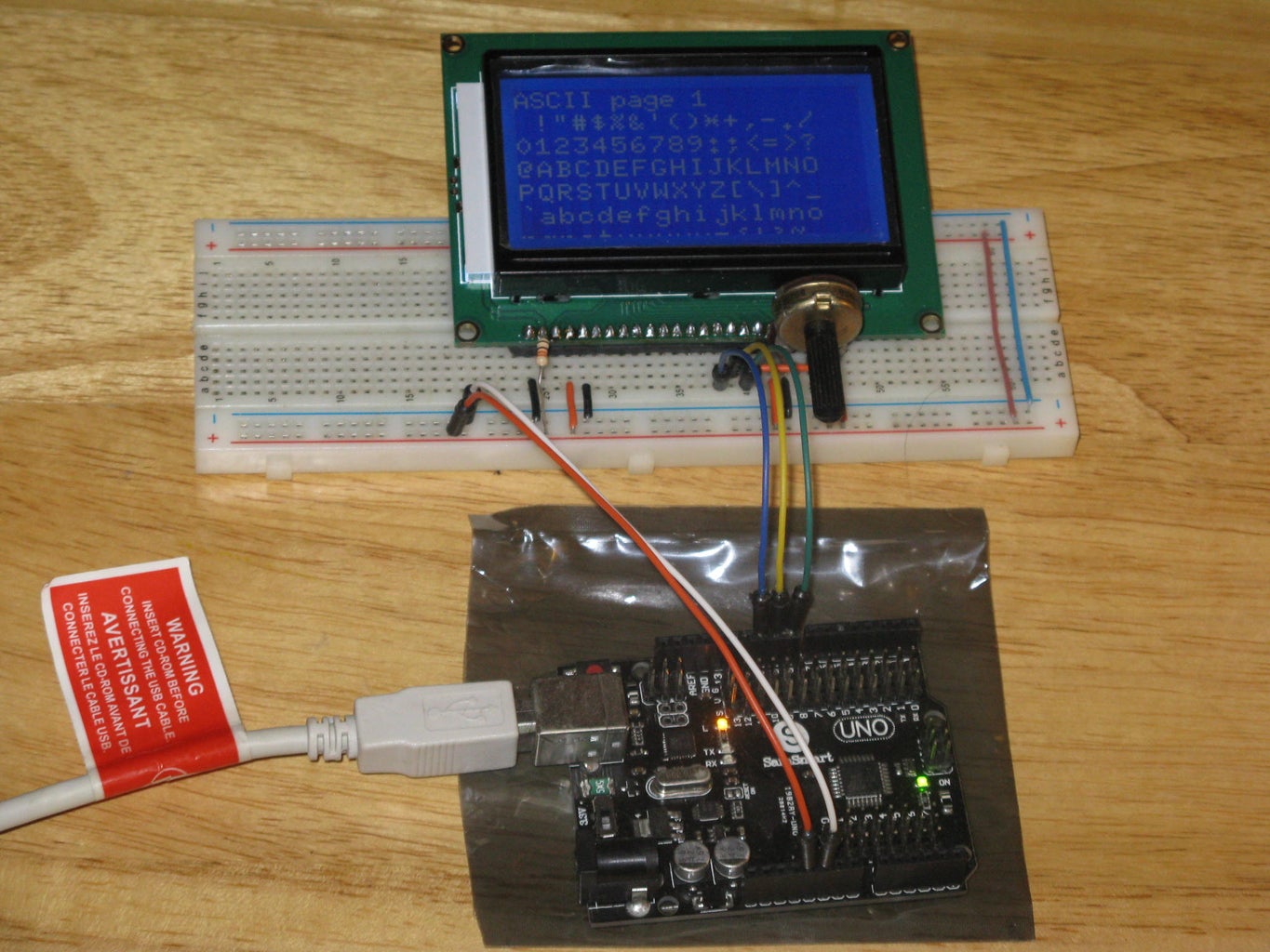
This time I wanted to find out if I could put the LCD controls where I wanted; so I changed the 3 wire constructor code from:
U8GLIB_ST7920_128X64_1X u8g(18, 16, 17); // SPI Com: SCK = en = 18, MOSI = rw = 16, CS = di = 17
To
U8GLIB_ST7920_128X64_1X u8g(10, 9, 8); // ENABLE, RW, RS
Pin 1 Gnd
Pin 2 Vcc
Pin 3 VO goes to the contrast pot.
Pin 4 RS goes to D8 on the Arduino board.
Pin 5 R/W goes to D9 on the Arduino board.
Pin 6 E goes to D10 on the Arduino board.
Pin 7 DB0 NC (No Connection)
Pin 8 DB1 NC (No Connection)
Pin 9 DB2 NC (No Connection)
Pin 10 DB3 NC (No Connection)
Pin 11 DB4 NC (No Connection)
Pin 12 DB5 NC (No Connection)
Pin 13 DB6 NC (No Connection)
Pin 14 DB7 NC (No Connection)
Pin 15 PSB NC (No Connection)
Pin 16 goes to Gnd
Pin 17 goes to Vcc
Pin 18 Vout NC (No Connection)
Pin 19 BLA to resistor 330 Ω ¼ W to Vcc
Pin 20 BLK to Gnd
And like I did in previous step, I uploaded the sketch.
At first the display was a bit funky from changing the digital pins; but once the sketch was uploaded the graphic LCD module started rotating through the different programmed screens.
Step 8: 4 Digital Pin Configuration


If you look around on the net you will find a number of different ways of connecting this graphic display to Arduino like this 4 digital pin configuration.
First I changed the 3 wire constructor code in the Arduino IDE sketch from:
U8GLIB_ST7920_128X64_1X u8g(18, 16, 17); // SPI Com: SCK = en = 18, MOSI = rw = 16, CS = di = 17
to
U8GLIB_ST7920_128X64_1X u8g(6, 5, 4, 7); // Enable=6, RW=5, RS=4, RESET=7
Next I changed the wiring to:
Pin 1 Gnd
Pin 2 Vcc
Pin 3 VO goes to the contrast pot.
Pin 4 RS goes to D4 on the Arduino board.
Pin 5 R/W goes to D5 on the Arduino board.
Pin 6 E goes to D6 on the Arduino board.
Pin 7 DB0 NC (No Connection)
Pin 8 DB1 NC (No Connection)
Pin 9 DB2 NC (No Connection)
Pin 10 DB3 NC (No Connection)
Pin 11 DB4 NC (No Connection)
Pin 12 DB5 NC (No Connection)
Pin 13 DB6 NC (No Connection)
Pin 14 DB7 NC (No Connection)
Pin 15 PSB NC (No Connection)
Pin 16 goes to Gnd
Pin 17 RST goes to D7
Pin 18 Vout NC (No Connection)
Pin 19 BLA to resistor 330 Ω ¼ W to Vcc
Pin 20 BLK to Gnd
And up loaded the sketch as in step 6.

Participated in the
Microcontroller Contest 2017


