

Introduction: How to Make a Solar Powered Fan!


More by the author:


About: Music, chemistry, electronics, etc.
(''Hooray! It's finally done. It's a bit late into the contest but we hope it is good!'')
This project is what we're entering for the Go Green contest. It's a cool solar powered mini-fan. The idea is that if you had a fan you would use the air conditioning less. And it's solar powered so that it has 0 emissions. Finally, this is the first of many collaborations between c3j1r0 and I.
As always, feedback is greatly appreciated. It's the sharing of ideas that keeps an open source community together. Also, ask any questions you have! We're always glad to help. Thanks in advance. And hopefully, enjoy!
Oh, and before we forget! A big thank you goes to PacTec Enclosures for the project boxes.
NOTE: Neither of our video cameras are working. :-(. Maybe we'll get a video up soon! I hope so.
Step 1: The Concept
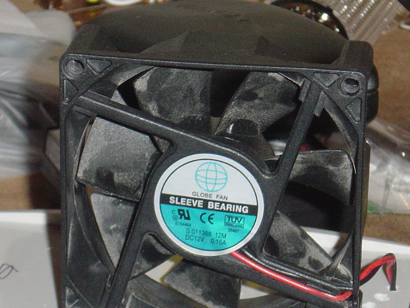
When we were taking apart an old computer (fun stuff!) we discovered a lot of very cool parts that we could use to make stuff. One of the cooler ones (sorry, very lame pun) was a 12V cooling fan. With the "Green Science Fair" contest running on Instructables we decided upon making a solar powered fan out of it. It's really pretty basic. We took a battery holder (2 AA batteries) and wired it into a 1.5V to 12V step up circuit. Now that we had it outputting 12V we hooked it into the fan. Finally (and this is what makes it "green"), we hooked a PV cell into the circuit so that it would charge the batteries. We knew how much energy air conditioning takes up, so we thought this would be a good way to get people to use less of it.
Step 2: Finding the Tools
"Finally," you say. "They've stopped talking and started on the actual project!"
Well, you are correct. We're done rambling for now. The project is actually starting.
Here are the tools you are going to need to build this (NOTE- Components are on the next step) (Also, you can download the checklist, it's the open office file. It would probably suffice just to read it, but if you had any questions you'd want to check out the stuff below.):
A Soldering Iron (And soldering station)
Wire Strippers (Or you could use this method. Trust me, the wire strippers are way faster!)
Wire Cutters (Mine were built in with the wire strippers)
*Optional* Pliers (The thinner the better, it makes it easy to grab things on your board without knocking other things loose)
*Optional* Third Hand Tool (Or a bench vise or something. There's a great instructable on how to make a third hand tool here)
*Maybe* A Dremel (You don't absolutely need this but you'd be surprised how much easier it is)
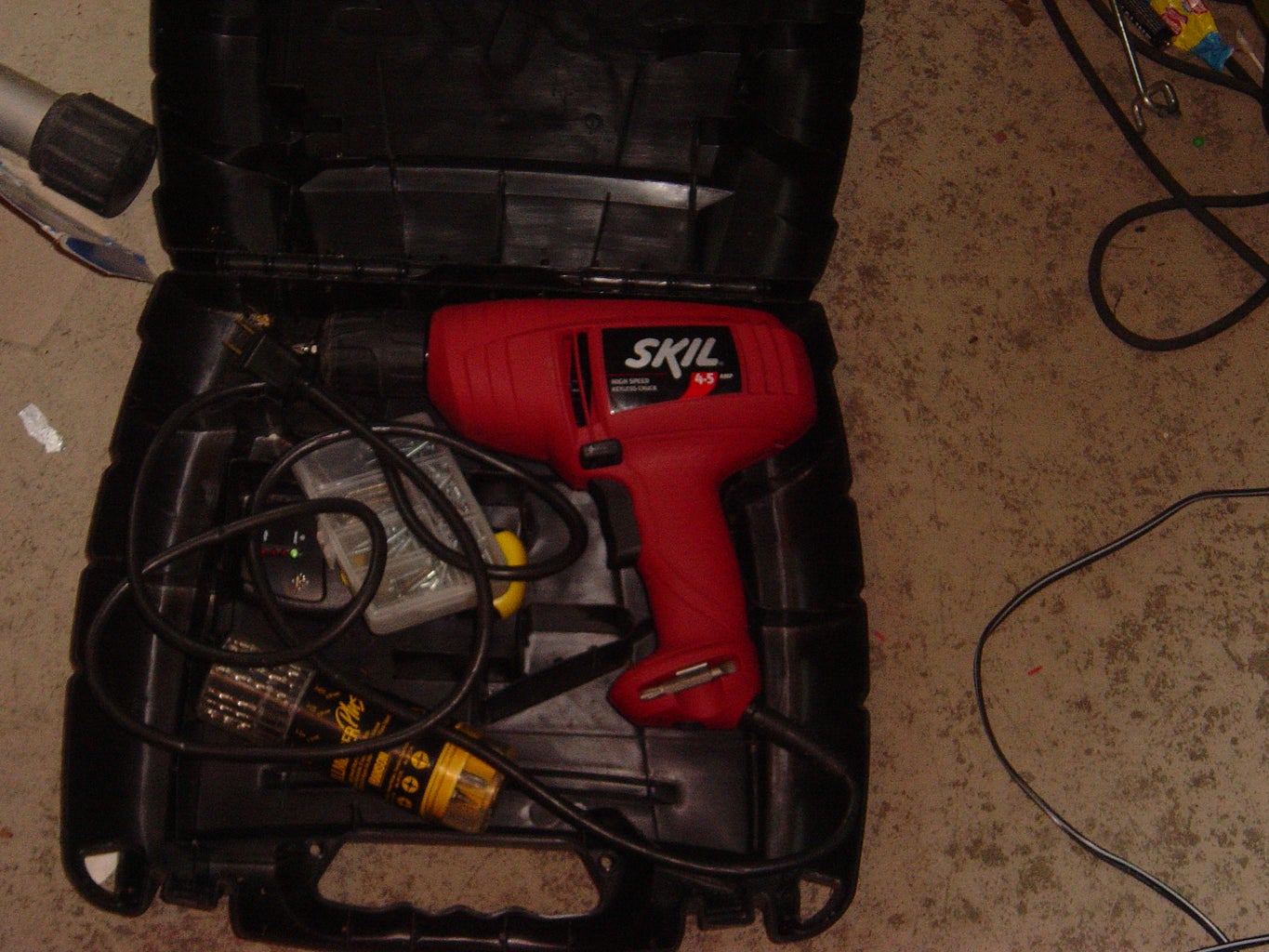
*Maybe* A Drill (You might be able to use your Dremel or find another way)
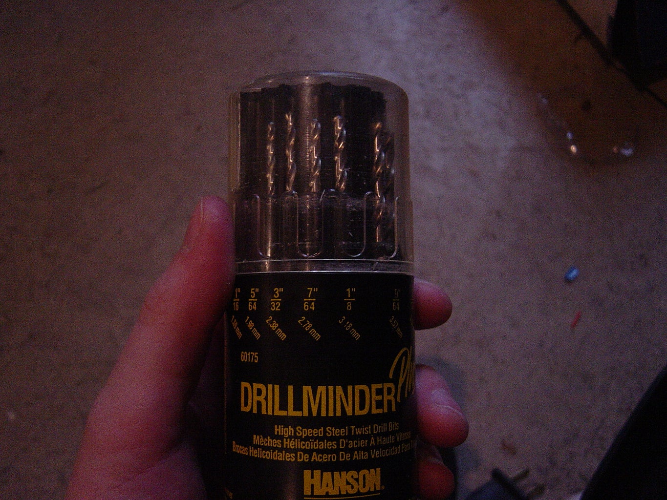
*Also* Various Drill Bits if you are planning on using the drill.
Once you have all of that it's on to the components!
Well, you are correct. We're done rambling for now. The project is actually starting.
Here are the tools you are going to need to build this (NOTE- Components are on the next step) (Also, you can download the checklist, it's the open office file. It would probably suffice just to read it, but if you had any questions you'd want to check out the stuff below.):
A Soldering Iron (And soldering station)
Wire Strippers (Or you could use this method. Trust me, the wire strippers are way faster!)
Wire Cutters (Mine were built in with the wire strippers)
*Optional* Pliers (The thinner the better, it makes it easy to grab things on your board without knocking other things loose)
*Optional* Third Hand Tool (Or a bench vise or something. There's a great instructable on how to make a third hand tool here)
*Maybe* A Dremel (You don't absolutely need this but you'd be surprised how much easier it is)
*Maybe* A Drill (You might be able to use your Dremel or find another way)
*Also* Various Drill Bits if you are planning on using the drill.
Once you have all of that it's on to the components!
Attachments

Step 3: The Components


These are relatively easy to find. The checklist for these is on the tools page. You could use that, or just read the info below. These can all be easily ordered from Digikey or bought from RadioShack. The only thing we had trouble with was the PV cell, which we took from a solar lawn light.
(1) Schottky Diode - Digikey Part # 1N5818-T
(1) 47 uF Electrolytic Capacitor - Digikey Part # P902-ND
(1) Linear Technology DC/DC Converter Chip - Digikey Part # LT1073CN8-ND
(1) 2 AA Battery Holder
(2) AA Rechargeable 1.2V Batteries - (These will come with your solar powered lawn light if that's the path you choose to follow)
(1) 8-Pin Socket - Digikey Part # 3M5461-ND
(1) 120 uH Inductor - Digikey Part # M10078-ND
(1) 12V, .15A Fan
(1) PV Cell - (Note: I would get this from a lawn light. See Step 4 for the details on getting this.
(1) PC Board -What ever size works for you.
A Project Box - Once again, any size. Probably something you could fit the fan on top of. (Thank you PacTec)
(Some) Wire - You'll probably want some that is threaded and some that is solid core. (More threaded! Solid breaks a lot!)
Step 4: The Solar Light


One of the hardest parts to find for the project was the PV (Photovoltaic [Solar]) Cell. What we ended up doing was biking (not driving!) to the local hardware store and buying a solar lawn light. So here's how we got the parts we needed.
1. Get the light. They sell these at most hardware stores.
2. Take it out from the box.
3. The parts you're looking for are the PV (Solar) Cell and any rechargeable batteries that are in there. Try doing most of it by hand. That way you probably won't damage the parts. The picture below is of us doing it... not by hand. Haha. If it comes to that, oh well. Any way will work!
4. The battery should probably just pop out.
5. You can desolder the Solar Cell, or just cut the wires. Either way.
So now you have all the parts you need.
Step 5: Check the Schematic


Now before you run off and start soldering everything together, you should print out your schematic. I would suggest keeping it with you while you solder.
The problem with this is that the schematic is rather confusing. The schematic that I used is the one from the LT1073 datasheet (2nd picture). If you just printed that out, you would be in trouble though. The spots where the schematic tells you to connect don't exist on the actual chip.
So... to solve this problem, what you need is another diagram (The first picture). It tells you where the connections that are named in the second diagram are located on the chip.
The third and final picture shows you how to put your entire circuit together. It's pretty straight forward.
Step 6: Resistor!

Here's the final step before you get to the actual construction. Also, I'm putting in a summary so you don't have to read the entire thing if you don't want to.
Summary: Wire a 10 Ohm resistor into the circuit, right out of the battery pack.
We want two batteries to power this so that it will last longer. The problem is that we are using rechargeable batteries, which output 1.2V as opposed to the standard 1.5V. This is a problem because it means that we can't use the 3V to 12V converter. We have to use one lower. So how can we do this without blowing out the circuit?
We need to use a resistor to lower the voltage entering the chip. The reason I'm telling you all of this is so you can adjust this if you make modifications to the project. After all, Instructables is a great community for sharing ideas. Odds are that someone will make modifications to this project. It's easier if they have all of the info. (Also, it's probably good for educational purposes).
The way that we determined what resistor we needed was through Ohm's law, which states V(voltage) = I(current) x R(resistance). We use it in this way...
The forward voltage of our circuit is 1.5V. We then divide that by the amperage, .15A (Amperes! not milliamperes!), and find that we need a 10 Ohm resistor.
Step 7: Start Constructing!

Now that we have everything we need ready you can start soldering the project together. Here are the steps we used to do this.
1. Set up the board in the vice/helping-hands tool.
2. Put all of the components in to see if they fit. (Note: Don't put the LT chip into the socket until the rest of the project is finished.
3. If they don't fit you should get a new board. Otherwise, solder them all to the board. (HINT! It's easy to solder the parts if you bend the leads so that they stay in the board.)
4. Now to start connecting the parts. You can really do this in any order you want. Check the next step for our suggested order.
Step 8: How We Did It.
This step is really just how we connected the parts on the board. You could do this any order that you wanted to. If you haven't done much soldering before then this could be a help. Otherwise, just connect it in whatever order you choose, and skip this step.
1. Cut and strip wires of different lengths. (You can set up a whole bunch now, or between steps when you need it. Whatever works for you.)
2. Using your schematic, figure out which pins on the chip you are going to be using, the connect wires to those. Just leave the other end of the wire open.
3. Now, start connecting the other ends of those wires to where they go in the circuit.
4. Once you've connected all of the wires that run from the chip you should start making the other connections. (Make all of the connections that don't involve the chip)
Now you should have the chip done. All that's left to do is to connect the battery, PV cell, and fan. Then set it up in the box and you're ready to go!
Step 9: Connect the Rest.


IMPORTANT Before you start this step you should remember that you are connecting parts that are going to be inside the box, to parts that will be on the outside of the box. The pictures in this step are just to show you how they connect. Remember to drill the holes in the box, put the wires through, then make the connection.
Now that you have the board with all of the components connected finished you can start connecting the power source and the fan.
The first and most important thing you should do is take out the drill and drill 2-4 holes (depending on the size) in the box.
Next we connected the PV Cell to the battery pack. Thread the wires from the PV cell through the holes, and into the box, then connect it to the battery pack.
(Remember, red (+) to red, and black (-) to black. The colors may not be right but if they aren't (or if you just can't remember), there's probably some sort of marking indicating which is positive and which is negative.)
Now we added the third wires that will go to the switch then the board on the positive side, or that will complete the circuit on the negative side. These will go inside of the box.
After that, connect the third wire on the positive side to the switch. Then connect the switch to the board.
Now you are almost done. Just attach the fan to the board (through the holes in the box) and finish off the circuit at the third wire on the negative side of the battery pack (inside the box).
And there you have it!
Step 10: Final Steps

There are a couple more finishing touches to complete the fan.
1. Test it out! Make sure it works by turning it on and off a couple of times.
2. Next, you're going to want to secure the fan to the top of the box. You can use hot glue or that foamy padded tape stuff.
3. As for the solar panel, you may not want to totally secure it to the box. This way, you can rotate it around so it gets the most sun.
4. Finally, enjoy your fan! Use less air conditioning! Relax in the hot weather!
Step 11: In Conclusion...
In conclusion, you have now completed your fan. Pat yourself on the back! Not only did you finish a fun project, but you also are helping the environment.
Remember, one of the reasons this project is good is because it is a very green project. What I'm getting at is that you shouldn't drive to get all of the parts. Bike or walk as much as possible!
Finally, use it! You're not being environmentally friendly if you make it then proceed to abandon it in the garage. Use it so you don't run your fan in your room as much.
And remember, feedback is always appreciated.
Step 12: Tips and Troubleshooting


This is the last step, we swear! It's really just a collection of tips and ideas that could help if you're having problems.
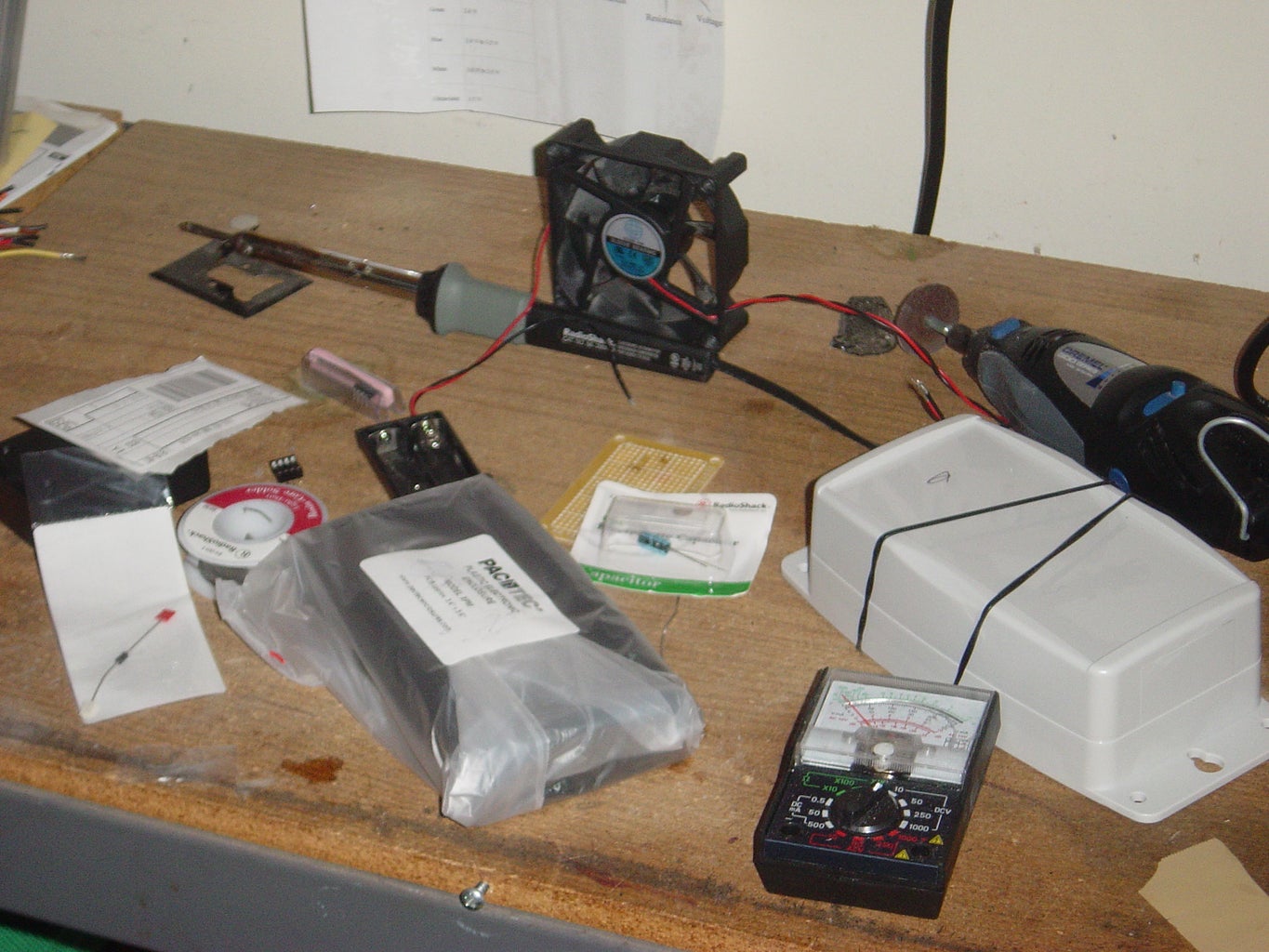
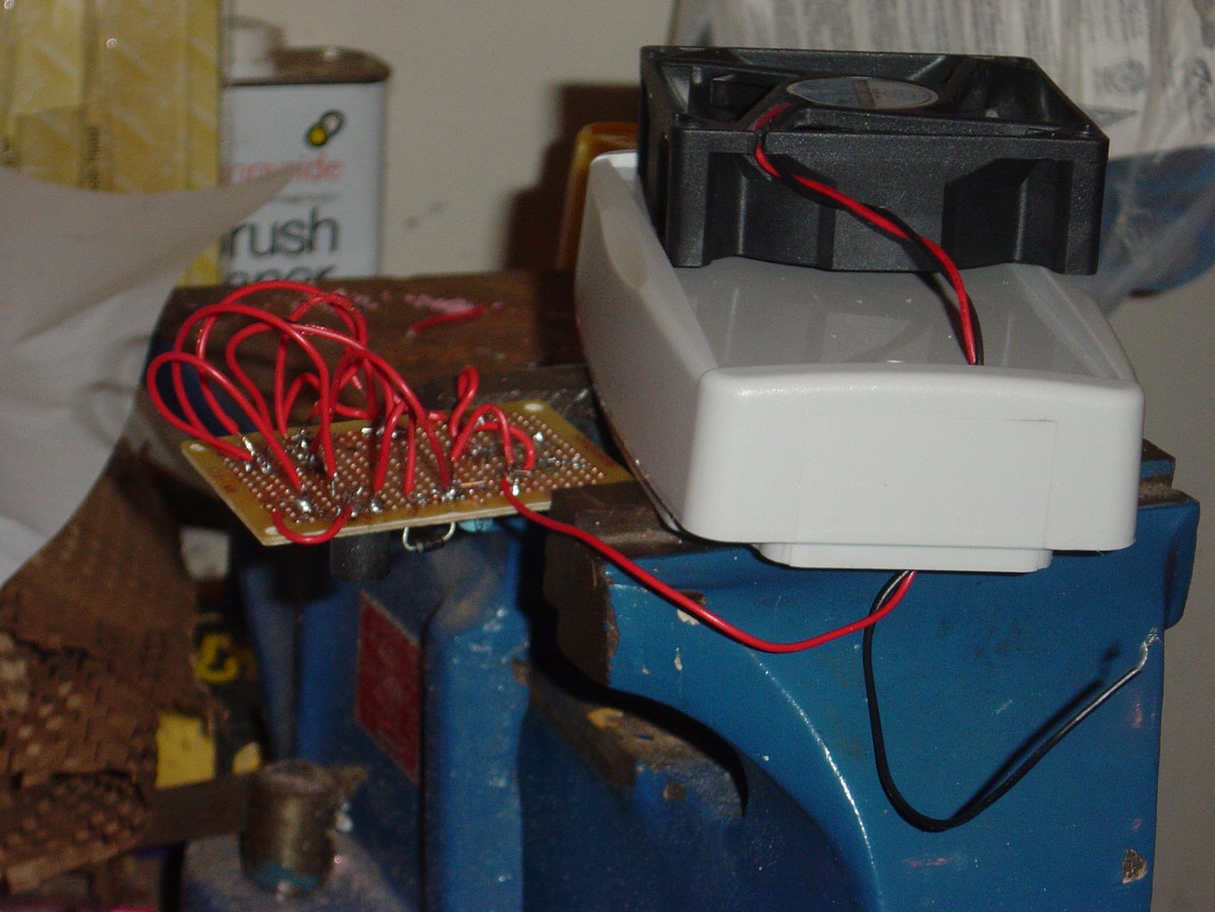
1 Have a clean workspace. Picture number one is our workbench. A perfect example of what not to do. I think we spent more time looking for parts and tools than actually building the project.
2 Enjoy yourself. You can make it a lot more fun by putting on some music. We hooked up Eric's iPod and played it way too loudly. Then the neighbors complained. Then we played it not so loudly.
Troubleshooting
_
1 Check your work with a multimeter. It would have saved us a lot of time if we had.
2 Make sure you get the right parts. We accidentally ordered our inductor incorrectly. We mixed up micro with nano. Don't do that. =P. It's a lot easier if you have the right parts.
