

Introduction: Traffic Light Without Arduino


How to build up a traffic light?
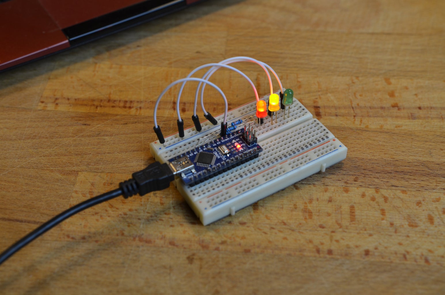
Today the question sounds easy. Three LEDs plus resistors and an Arduino. Nothing more like seen here: link.
But how to build up a traffic light with discrete parts?
There are a lot of circuits around:
- Talking Electronic: 4 Way Traffic Lights
- Electronics Club: Traffic Light Project
and so on.
Why to build a new one. My son always claims that with the circuits above either the red and green phases are to short or the yellow phases are to long.
For my new setup I have the following requirements:
- Individual adjustment of the red and green duration and the yellow ones
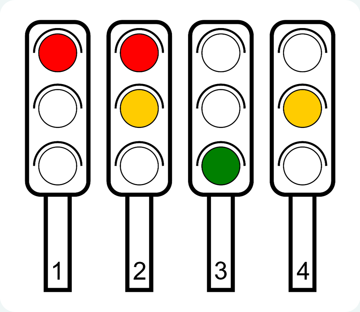
- Full German 4-phases standard with red - red/yellow - green - yellow.
Step 1: Full Circuit


I setup the circuit on two small breadboards. Because of the complexity I only draw a classical circuit diagram with fritzing.
For an easier explanation of the functionality I divided it into three parts:
- Stepper
- Timer
- Output
These are shown in the next steps.
Step 2: Stepper

As in the other circuits the CD4017 (Decade Counter) is used to run through the phases. But I use only the outputs 0 to 3 for the four phases. The fifth output (4) resets the chip to 0. For my setup the CD4050 (Hex non-inverting buffers) is not really necessary but with it's possible to use more than one led per color.
This section has one input (Signal) and 8 outputs (red, red/yellow,... and LED red, LED red/yellow,...).
First to the input...
Step 3: Timer

The Timer based on a classical NE555 Astable Multivibrator. The output of the timer goes into the Signal input of the stepper. But to adjust the frequency individually I used the four outputs (red, red/yellow,...) of the Stepper as inputs to feed pin 7 of the 555 with different voltages. There are two potentiometers to adjust the voltage divider on pin 7. The red/green and the both yellow phases feed one potentiometer input each. And because the frequency of the timer follows this equation
frequency = 1.4 / ((R1 + 2R2) × C)
with R2 = 22kohm, C = 2.2 µF and R1 = P1 or P2 you can set two different durations.
Step 4: Output

There are four outputs left. These are the outputs for the three LEDs.
Four outputs for three LEDs?
How this works?
With diode steering!
With three diodes you can guide the signal to the individual LEDs. Comming from the four inputs and go through the circuit with your finger. Follow the arrows in the diodes and see the bars as barriers. You will understand the principle.
Here's also a nice video on diode steering: link
Step 5: The End
Now everything is finished! Connect a 9V battery and the traffic light is running.
But ... my son claims that normally a traffic light is used on a crossing - back to the beginning ;)


