

Introduction: Transistor Basics - BJTs


Transistors are arguably the most important electronic component in use today. They are the reason we have the technological advances we have today. Without them, there are no radios or computers, and in turn there are no modern TVs, phones (smart or dumb), or cars. Life would be drastically different.
Over the years manufacturing techniques have been able to make smaller and smaller transistors to the point where you can only see them under magnification. Your phone alone has millions by itself. The Cortex A9 processor is widely used in smartphones and tablets and has 26,000,000 transistors (reference). The XBOX One processor has 5,000,000,000. That's 5 billion. In 363 mm2. That's just a bit smaller than a U.S. postage stamp (418 mm2)
But what do they do? Why are they so important? More importantly, how do I use them in my own projects? My aim is to answer those questions in a clear and concise way so you can get back to your projects.
Before we begin, I want to clarify. This Instructable is only going to cover the basics and is not intended to be a thorough text on all of the theory and math behind how transistors work. If you wish to learn more on that, check out the transistor pages at electronics-tutorials.ws and allaboutcircuits.com.
There are also several types of transistor, with the two most common being the bi-polar junction transistor (BJT) and the Metal-Oxide Semiconducting Field Effect Transistor (MOSFET). They are both extremely useful and very similar in function, although there are many differences. I will begin here with BJTs. Click here for my MOSFET I'ble.
Step 1: Some Parts and Then Some Theory.


There are many, many types of BJTs out there, and most of them are interchangeable with each other for the vast majority of projects, as long as you match types properly. That means that the parts list is totally up for interpretation according to what you happen to have in your parts bin at home.
You will need -
+ NPN and PNP type transistors. For the sake of these demos I will be using 2N3904 (NPN) and 2N3906 (PNP) for nearly everything as these are extremely easy to get your hands on. Any differences will be noted. 2N2222 BJTs can be used for the 2N3904 and 2N2907 can be used for the 2N3906 if needed.
+ various resistors - a range of values from 100-100kΩ will work nicely. Exact values will be given as needed.
+ other bits - LEDs, motor, speaker, flex sensor, electret microphone, audio transformer, etc. Basically components that require some amplification to be useful, or require more power than the circuit can provide. Some of these will be used, others are suggestions for your own projects later on. Details will be given in the demos.
+ breadboard - none of these demos is meant to permanent, so get a breadboard for ease of building
+ jumper wires - for connecting bits together
+ 9V batteries and battery connectors - for power
Images 1 and 2 are diagrams for both types of BJTs - NPN and PNP. The three pins are labeled as Base, Collector, and Emitter (FYI - for FETs, these are labeled Gate, Drain, and Source and serve the same functions). Carefully note the orientation of the three pins in the image 3. Datasheets are your friend and will save lots of headaches. Always double check the datasheet for the BJT you are using since some use a different pin configuration. I'm always getting the pins crossed anyway, which for most projects won't be an issue if you catch it quickly enough, but it's best to avoid it. Here are the datasheets for the 2N3904 and for the 2N3906.
As always there is a lot of information on the datasheets. Pay special attention to the maximum ratings. Don't operate near max ratings if you can avoid it, always giving yourself some room. Now look at image 1 again. In order for NPN BJTs to work, the base voltage (Vb) must be more positive than the emitter voltage (Ve). And the collector voltage (Vc) must be more positive than Vb. Going back to the max specs for the 2N3904 from the datasheet, we see that if Ve is 0, Vb can be no more than 6V more positive than that. And Vc can be no more than 40V more positive than Ve. Vb must be somewhere in between Ve and Vc for the BJT to work. The Vb threshold for many BJTs is about 0.7V, meaning that at that voltage they begin to open. Also, the nature of BJTs is that while you will need a minimum of about 0.7V to turn it on, the current through the base is the defining factor for performance. As the base current increases, so does the collector current. This is different for MOSFETs, which work more on gate voltage than current.
For PNP BJTs to work, reverse all of that from above. Vb must be more NEGATIVE than Ve, and Vc more NEGATIVE than Vb. A little trick to help remember is to remember the type you are working with. NPN require Positive voltage and current, and PNP require Negative voltage and current.
BJTs need to be protected from too much current, just like any other component. Don't ever connect the emitter and collector pins directly between the power supply and GND. Always put a component with resistance in series. Going back to the 2N3904 datasheet, we see a max collector current rating of 200mA, but in the bullets under features on the first page it says 100mA. That is an ideal figure and it's not a bad idea to use that as a self-imposed max value. Again, stay away from max limitations by using resistors. Obviously we will be operating at much lower than max for these demos.
Image 4 shows a different type of packaging for BJTs. The smaller package, like in image 3, is known as the TO-92. The larger style is the TO-220. These packages are used in many applications besides BJTs and FETs, so don't assume that since it looks like one, it is one. Always check your part numbers. The difference is that the TO-220 can handle much, much higher current loads than the TO-92 if properly paired with an appropriate heat sink. I have some that are rated for 30A as opposed to 0.2A. There are still many more types of cases for transistors, if you're interested, and you can even get them as arrays in an IC package on one piece of silicone, like the LM3046.
Step 2: Electronic Switches


In their most basic function, BJTs are switches. By applying a small current at the base, we can get a much larger current to pass between the collector/emitter pins. Since transistors typically don't draw very much current, they make a great electronic switch instead of needing a mechanical one.
Image 1 shows a simple LED driver schematic using the 2N3904 NPN BJT. In my testing, I measured a base current of 0.640mA, which would normally not be enough to turn on an LED. But the LED was nice and bright, with only 7.4mA passing through it.
Build: Place the BJT on the breadboard with the flat side facing you. The left pin is the Emitter, the right pin is the Collector, and the middle pin is the Base. Connect the 10kΩ resistor between the switch and the base pin. Connect the 1kΩ resistor between the collector pin and +9V. Connect the LED between the emitter pin and GND, with the flat side of the LED, the cathode, connected to GND. Connect the other side of the switch to +9V. (Image 2)
Push the switch, a positive voltage and current are available at the base pin, which closes the connection between the emitter and collector, allowing current to flow between them and turning on the LED.
Now let's use a PNP transistor and see what we have to change (image 3). Try swapping it straight out and push the switch. Anything? Nope. Remember that the PNP BJTs need a relatively negative voltage at the base to work, so one change is that the switch has to be connected to GND instead of +9V. The other difference is that while the pin assignments are the same between NPN and PNP BJTs, the pins are NOT in the same orientation in the schematic. Look at image 1 and see that the emitter (the arrow pointing away from the base) is on the bottom near the LED. Now look at image 3 and see that the emitter (the arrow pointing toward the base) is now at the top near R2. Simply turn the flat side of the PNP BJT away from you and put it in the same three pins the NPN was in. (Image 4)
Since a much higher current can be driven between the collector and emitter, we can use transistors to drive much larger loads than the circuit may be able to handle on it's own. Image 5 has a schematic for doing just that. R2 is not absolutely necessary since the relay has some resistance to protect the BJT.
Step 3: One-stage Amplifiers


Remember when I said that for BJTs to work, you need a small current at the base pin to allow a much larger current to flow across the collector and emitter pins? Small current in, large current out... that's an amplifier. The basic formula to determine the gain is to divide the output by the input. In our example earlier with the LED, a small current of 0.640mA allowed a larger current of 7.4mA to flow through the LED. In this specific example, the gain would be 7.4mA / 0.640mA = 11.56. In the datasheet, the built in gain of the BJT is labeled as hFE and is known as the DC current gain (pg 2 under "ON characteristics"). As you can see from the datasheet, the actual gain is determined by the base current, the collector current and the voltage across the collector and emitter. Some DMMs will have a function to allow you to test the open-loop gain of BJTs (image 1), though I have no idea what the test conditions are for each DMM.
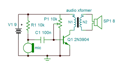
Image 2 shows a schematic for using an NPN BJT as a simple one-transistor amplifier. You will need an electret mic and an audio transformer with a 1kΩ primary and an 8Ω secondary. The circuit itself is not very powerful, and is better used as a simple demonstration.
Build: Place the NPN BJT on the breadboard with the flat side facing you. Connect one end of the 100nF (104) ceramic capacitor to the base (middle) pin of the BJT. Connect the positive pin of the mic to the other side of the capacitor and connect the other pin of the mic to GND. Connect a 10kΩ resistor between the positive pin of the mic and +9V. Place the 10kΩ potentiometer on the board. Connect one side pin to +9V, the other side pin to GND, and the wiper (middle) pin to the base pin of the BJT. Connect the left pin (emitter) of the BJT to GND. Connect the right pin (collector) to one of the primary coil pins on the audio transformer. (If the primary winding is center-tapped, don't connect to the center tap. Use the full primary winding.) Connect the other side of the primary winding to +9V. Connect the speaker across the secondary winding pins. (Image 3)
The potentiometer will allow you to tune the circuit so that it works. It is a rather small window where it works, so take your time. As you adjust the pot, tap or rub the mic. Put your ear near the speaker as you adjust so you can hear it when you find the sweet spot with the pot.
The mic works by generating a very small voltage when sound waves hit it. This changing voltage allows the capacitor to charge/recharge very quickly according to the RC time constant established with the potentiometer. This translates into a current at the base pin of the BJT, which as we know will allow the current to flow between the emitter and collector. The transformer then steps the +9V down while increasing the current high enough to drive the diaphragm on the speaker.
Image 4 shows the response of the mic when I blew on it. It peaks at about 5mV. Image 5 shows the voltage across the speaker at the same moment. The max now is about 20 mV, so a gain of about 4. It's not much, but it was enough to hear it. Next we'll add another amp stage and get even more out of it.
This circuit can also be used with a small flex sensor. Just replace the mic with the flex sensor and remove the 10kΩ resistor as it won't be needed.
Step 4: Two-stage Amplifiers
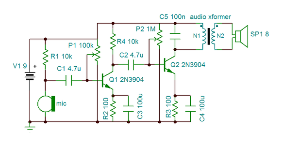


As is usually the case, if one is good, two is better. In this case, we can definitely improve performance of the amplifier if we add another BJT. Let's see how that would work. Image 1 is the schematic.
Build: We're going to build off of the circuit from the last step. Disconnect the transformer and speaker from the circuit and set aside. Swap C1 with a 4.7uF electrolytic capacitor and the 10kΩ potentiometer with a 100kΩ potentiometer. Connect a 100Ω resistor and a 100uF capacitor between the emitter pin for the first BJT (Q1) and GND. Place a 10kΩ resistor between the collector pin of Q1 and +9V. Connect a second 4.7uF cap between the collector of Q1 and the base of Q2. Connect the two outer pins of the 1MΩ potentiometer between +9V and GND and connect the wiper pin (middle) to the base of Q2. Place a 100nF (104) capacitor between the collector of Q2 and +9V. Place a 100Ω resistor and a 100uF capacitor between the emitter of Q2 and GND. Connect one side of the primary winding for the audio transformer to the collector pin of Q2 and the other side of the primary to +9V. Place the speaker across the contacts for the secondary winding. (Image 2)
The 100kΩ pot is for tuning the circuit. Again there is a small window where it will work, so take your time. You should here some squeals or pops as it gets close. Tap or rub the mic as you adjust so you can hear it. The 1MΩ pot is for volume, and it works very well. As you can see from the two scope images, the data from the mic looks like it did in the last step, with most of the data within about a 1-2mV swing, and peaking at about 4-5mV (image 3). The output across the speaker looks much different. Before we had a max of about 20mV for a gain of about 5. This time our peak values are about 400-500mV, with most of the data between 100-200mV. That shows a gain of 100 for the circuit and a 5X increase in gain from the last circuit (image 4).
Step 5: Power Amplifier


Clearly BJTs are great at amplifying, but sometimes we just need more power. The last circuit is great, but what if we have a larger speaker? A small 8Ω speaker will work just fine for the last circuit, but what if we want some volume? Suppose we salvaged some 4 in. or 6 in. speakers from... whatever it was and we want to use those. Speakers that large could draw way too much power from our little circuit and could very well cause some damage to the components. So, what do we do? We build a class B amplifier, that's what we do!
The class B amplifier is ridiculously simple (image 1). I used it before in this I'ble, and I'll keep coming back to it as it's just so elegantly simple. In it's basic form, it's just two high current BJTs in TO-220 packages, one NPN and one PNP. This circuit assumes that your input has both positive and negative voltage swings, like a true sine wave.
You will need high current BJTs for this. I like the TIP31C (NPN) and the TIP32C (PNP), but that's mostly because I happen to have them in my parts bin. You will also need some form of sound generation (like a waveform generator), + and - 9V sources, and a speaker. Take a look at the datasheets for the TIP31C and the TIP32C to get the pin assignments as they are different than the smaller TO-92 packages. Looking at them with the tab toward the rear, the pins are base, collector, emitter from left to right. Again, double check the datasheets.
Build: Put both BJTs on the bread board such that no pins are connected to each other. Connect the base pins together with a jumper wire. Tie the emitters together with a jumper wire. Connect the input from your circuit or wave generator to the base pins. Connect the two batteries in series, with the '+' from one connected to the '-' of the other. This junction is now GND. Connect the battery GND to the circuit GND so everything is in the same plane of reference. Take the unconnected '-' lead from the battery pair and connect it to the collector of the TIP32C. Connect the unconnected '+' lead from the battery pair and connect it to the collector of the TIP31C. (Image 2)
I tested this circuit with a 1" speaker and with a 5" speaker and got nearly identical results. The test signal was a 4V0-p sine wave at 200 Hz. Images 3 and 4 show the distortion in the wave due to the characteristics of the speakers when there is no power amplifier connected (image 3 is the smaller speaker). When the power amp is connected, we see a much better output, as shown in images 5 and 6 (image 5 is the smaller speaker). But there is still some distortion and the 4V input has been dropped a bit by the threshold voltage of the BJT. How do we fix that?
Image 7 shows the same circuit, but this time with an op-amp connected as a voltage follower. This will ensure that the voltage stays the same from input to output, while still allowing the BJTs to do their job of providing more current for the speaker to use. This is especially useful at higher frequencies. Between images 8 and 9 you can see the difference the voltage follower makes in removing distortion at high frequencies. The input here was a 2kHz sine wave with the same amplitude as before. The 5" speaker was attached to the output. And yes, it was really loud.
Step 6: Oscillators


BJTs are wonderful for oscillating circuits because of their ability to turn on and off based on the voltage/current at the base pin. There are numerous applications for this, but we'll look at a couple here.
The first is an LED flasher (image 1). This can be used for either one or two LEDs and the flash rate is fully adjustable for your own application.
Build: Place two PNP BJTs on the bread board with the flat side facing you and no pins connected to each other. Put a 10uF capacitor between the base pin of one BJT and the collector pin of the other, with the cathode of the capacitor connected to the base pin. Place a second 10uF capacitor between the other base/collector pin pair in a similar manner. Connect a 100kΩ resistor between each base pin and GND. Connect a 470Ω resistor to each collector pin and then an LED between each 470Ω resistor and GND. (Image 2)
As shown the LEDs will flash at about 1Hz. Changing either capacitor or either of the 100kΩ resistors will change the flash rate of one or both LEDs, so you may want to use variable capacitors and/or potentiometers to play around with this circuit. The thing about this circuit is that if one LED is on the other is off, but one will always be on. You get no period of time where both are on/off at the same time. If you only want to use one LED, remove one and tie the associated 470Ω resistor directly to GND. If you want to stack several LEDs in series, this circuit can handle it, limited by the voltage rating on the capacitors and BJTs, the collector current rating on the BJTs, and the amount of voltage you can provide. I built a 4 LED flasher, set in a rectangular shape with alternating corners flashing for a reader board for my work.
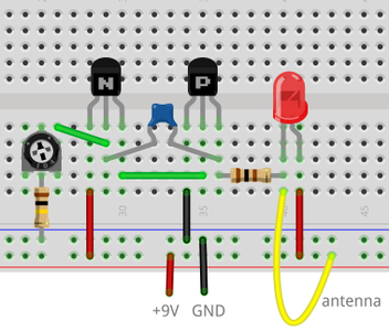
Another application for oscillators is in radio circuits, both for transmitting and receiving. A simple 2-transistor, AM frequency transmitter circuit is shown in image 3. (Disclaimer - If you decide to build a transmitter, be aware of any local laws that govern transmission of the resulting waves. The circuits I provide shouldn't transmit beyond the other side of the room, but that doesn't mean that they can't be modified by the savvy hobbyist, so know the laws and whatever happens as result is on you.)
Build: Place both BJTs on the board such that no pins are connected. Connect the collector of the PNP BJT (Q1) to the base of the NPN BJT (Q2). Put the 10nF (103) ceramic capacitor between the collector of Q2 and the base of Q1. Tie the emitter of Q1 to +9V and tie the emitter of Q2 to GND. Attach one end of a 100Ω resistor to the collector of Q2 and then connect a length of coiled wire and an LED between +9V and the other end of the 100Ω resistor. Connect the base of Q1 to one side of a 1MΩ potentiometer. Attach the wiper of the potentiometer to one end of a 100kΩ resistor and the other end of the 100kΩ resistor to GND.
The LED is there to let you know you have found the sweet spot on the potentiometer for getting the thing tuned right. Place a small transistor radio in the AM band nearby to pick up the signal. The circuit should work without the wire antenna, but it helps.
FM transmitters are pretty easy to build as well, though I will refer you to a search of Instructables and Google and let you filter the results as you see fit. A couple that really got my interest were from Make: and from I'bler ASCAS.
Step 7: But Wait, There's More...
But not from me though. I've gone over several simple uses for BJTs, and there are still more. You can even build your own op-amps and 555 timers if you wanted to.
Thanks for reading. Please don't hesitate to ask questions in the comments below. You never know when someone else has the same question and that way we can all learn and help each other get better. Have fun building!
Also, please check out the Digilent blog where I contribute from time to time.


