

Introduction: Renault [M9R] Removal of Broken Diesel Injector Casings
![Renault [M9R] Removal of Broken Diesel Injector Casings](https://content.instructables.com/F07/5FAE/IK7C7DRF/F075FAEIK7C7DRF.jpg?auto=webp&fit=bounds&frame=1&height=1024auto=webp&frame=1&height=300)
![Renault [M9R] Removal of Broken Diesel Injector Casings](https://content.instructables.com/FG8/7RB1/IKCV5VMG/FG87RB1IKCV5VMG.jpg?auto=webp&fit=bounds&frame=1&height=1024auto=webp&frame=1&height=300)


If there has ever been an engineering head-ache it certainly is this one - The funny thing is, it's a problem that has been remidied on some vehicle makes but remains unsolved on others [Mercedes CDI] -[Renault DCI 8 Valve F9Q] - [Renault 16v DCI M9R] The Latter is what this instrcutable will cover & illustrate.
Diesel Injectors: The Problem Occurs, because of electrolyte in the form of Rain Or Salty Air from the road - The battery Circuit in the car & The Electro-potential Between Iron & Aluminum.......Fe+AL+H2O......= A Galvanic Cell & Injector Seizure Caused By Oxidation Products of both the Steel Injector and Aluminium Cylinder Head.
There are many means of injector removal [1.Slide Hammer With Extraction Tool] A [2.Hydraulic Puller] & [3.Heat, Not Advisable] ---All of these have a cost if they are unsuccessful. Cam-Shaft Rocker Cover Damage, [Not Advisable as the cover has the upper Cam-Shaft Journals Bulit Inside // [But Breaking Injector Top Off,- Is Desireable For This Instructable, but is also costly ] .....
Why Would We Need to remove Injectors //Timing Belt Failure, Gasket Failure Or Injector Failure...........!
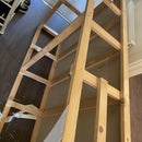
Step 1: Tools Required:


Above Is An Image Of Tools I Have Made Or Acquired..... From Left To Right [Not Listed In Order Of Use]
[1] Pin Punch [exstended with a bar] and sharpened Like a Very Small [Wood Chisel-3-4mm]
[2] X2 16.5MM Drill [1] STD & [1] with very shallow cutting angle 5-10o not 180o.See Image 2
[3] 57/64 Drill & Adapter or use 22.5MM
[4] 23/32 or [18mm]
[5] 14mm Masonary Bit [Carbide]
[6] 13mm Bit
[7] [2] 5/16 Punches Or Rod [1] [Modified] to sit onto Injector Spray Nossle [4MM Shallow Hole In Punch Face] See Image 3
[8] Hammer
[9] Pedistle Drill [With Groved Bed]
[10] 2 Pieces Of 6mm Hard Board
[11] 10mm X 150mm threaded Stud & Nut [With Spacers] & A Threaded 1" Square of Metal For The Drill Bed Slot ....... This Is For Bolting The Cylinder Head To The Drill Bed.........See Image No. 3
[12] Safety Glasses & Overall Maybe Gloves
[13 Air-Line Or Compressed Air Spray Can for Dusting.
[15 Angle Grinder & Magnet
[14] Torch Important Note: Patience Is A Must Have !!!!! + An Eye For Detail And Knowing when To Stop!!!!!!!!!
Step 2: Successful Drill Sharpening


I do not use a drill jig they take ages to set up and matching the mirror angle, is sometimes impossible. For years people have asked me, "How do you do that, I'm useless at sharpening drills......" I simply show them...... an easy referrence point is to place your first finger on the outer edge of the drills flute. See Image [1] Then mate drill cutting angle against 90/o Lower Portion of your wheel. Now the Drill Shaft is now approx. at a 58/o angle to the wheel.
Image [2] shows a side on view of the Drills Cutting angle to the wheel, it is nearly [90/o] you need a .5-1/o increase in this angle otherwise it will not Cut-a Greater angle makes a very Ferocious Unforgiving Drill. You should not see any gap between the Drill and wheel if you are cutting at correct angle. Image [4] Shows a perfect angle
To achieve symetry is easy!!!! The first image shows a finger in the
flute, once we see a flat knife edge we spin the drill backwards [Anti-clock wise] again we mate drill edge with wheel and gring until equal. ///do the same with the Rake Angle. It is easy to keep checking the drill widths whilst sharpening.....I have the wheel spinning continuously, whilst I am performing this feat :-) Practice Makes Perfect!!!!!!!
Image [3] is the Rake /Back Angle, this is achieved by dropping below 90/o you will now see a 2mm gap parallel with the cutting angle -if you do not do this the back angle protrudes and your drill will not cut.
Image [5] is a plan view of the drill, showing equal symetry on the drill cutting tip.
Step 3: Setting Up the Cylinder Head for Drilling


Take the [2] Pieces Of Hard Board to support /raise the head, also to protect and level the head with valves still in.
locate and align- Head Bolt Hole Near which ever injector has to be drilled out //Now place threaded Stud through this hole and screw into drill bed /// then lightly tighten [So Head Is Still maneuverable] use spacers to protect cylinder head bolt washer location, now screw on Nut.
The first drill that you need is a nice sharp 13mm drill -the injector shaft has a fair sized hole [it injects] this acts as a pilot for our 13mm drill [drill speed is @ 155 RPM Low] Make sure the injector top is flat, or the drill with go off centre [Use an Angle Grinder to Flatten------the centres should be checked before full drill depth is carried out. Even when you are sure its A Bulls Eye!!!!! ....This Preceedure is not successful without having due care and attention at all times..........Start with gentle drill pressure and check for parallel centres left by your light cut -Proceed If Edges are equal....
I do not use lubricant as I have found this creates [Case hardening /From The Carbon In The Oil] Just light Pressure, and A Sharp drill / Use your Air Blower Often & Magnet.
Drill Depth// Injectors have very hard internal parts, which cannot be remove untill drill depth is achieved///luckily for us Drill depth is achieve when the drill stops cutting as the first obsticle prevent us going any further [NEAT!!!]
Next We increase our diameter [Use 17MM Drill] Our drill has to be sharp!!! Following Proceedure above Drill A little then check Centre to Edge Is Parallel Referrence image [6] as example..... Proceed when you are sure your happy with Centring..........Drill Sharpening Has To Be Carried Out Reasonably Regular. Hard piece of injector internals will prevent further depth being achieved.
Step 4: #2 Drilling Continued


When we have drilled to the depth requires- certain squealing noises start - this is an indication that we have hit the most hard part of the injector internals - illuminate and take a look (you should be doing this throughout the drilling procedure. Do not worry it takes over an hour per injector if you are lucky and careful.
Insert your Air-line Blower nozzle and relieve any hard parts that may now be free (Small Spring, Rods & Caps) We should now be at a depth of 2.07"(52.8mm) Some times if we are central and lucky the drill breaks the injector casing [Shell] and the first piece [1] is free.....A circlip sits on the outside of the injector at this depth, this is why it breaks off. Now we proceed for about .5" (12.5 mm) we should hit a the hard piece below. Piece [4]
Now we take our 14mm masonry piece and start drilling with more applied pressure, check regularly this is only for 5/16" (8mm) depth. Pins should be visible and the drill will seem like its free spinning! Now place 16.5mm drill in chuck and drill to this stop -this opens the diameter at the bottom. Unclamp the cylinder head and turn over so you can see the valve heads. Now locate injector nozzle [poking through head] & use modified punch, See image [4]
[If The Right Depth has Been Achieved, when you locate the punch and tap with hammer this should tap through and free the stubborn nozzle! .Piece [5] & [4]. If Not Drill A Few MM Deeper with Masonry Bit & Then a little More With The Flat 16.5MM Bit...Try To Punch Through Nozzel Again. Having Successfully removed nozzle, (Blow the main injection pin out) Piece[6] Now proceed with 23/32 (18mm Drill) [Carefully !!!-Checking as you go---4" (100MM) is now a critical depth Stop when you have reached this depth ...Here you need patience OR A NEW CYLINDER HEAD...Image [1] show an illustration of Injector housing Diameters and Depth.
Step 5: Part #3 Drilling Continued


Use First Image above As Referrence for items. If Items 4,5,6 have Successfully Dis-lodged then we can now pro
ceed to the final stage which is CRITICAL & Crucial to successful Injector Removal - We continue drill with our 16.5mm [118/o] drill bit until we feel a the drill vibrating ---stop and check regularly -using illumination if you see a hexagonal shape appear, then we are close to the injector washer seating of the injector [Image5]. Item stop when you can see the washer base is close. [8] -Now we move on to a Flat Angled Drill Total Angle is 175/o Sharpen 16.5mm Drill to this angle Otherwise we will breach the Injector seating. Here we use the copper washer underneath as our guide to depth, it is easy to see................At this point we may be lucky, that the drill lifts up this remaining piece [Image 7] or we have to help it on its way, by once again turning the head upside down and using a flat 5/16 punch to release washer through nozzel hole in Cylinder Head.......See Item [8-9]
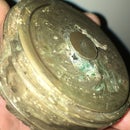
If you have arrived at a successful conclusion then you will have something which resembles Image [1] ,Image [2] & Image [3]
Happy Hunting --this instructable has been quite a challenge to put together as there are so mant areas and angles to cover especially if this is not familiar to you // Positive comments would be welcome // this instructable would save you fortunes in cash if this ever happens to you Or a friend :-D


