

Introduction: ULTRASONIC RADAR SYSTEM USING ARDUINO


The circuit described here demonstrates the working of a ultrasonic based radar system. It uses ultrasonic sensor to detect an object and measure its distance and rotates according to servo motor.The angle of rotation is displayed on a 16x2 LCD screen.Whenever the obstacle is detected,the buzzer turns on and it is also displayed in the LCD display.
Radar systems have a number of defence as well as civil applications.
A radar system consists of a transmitter that transmits a beam towards the target, which is then reflected by the target as an echo signal. The reflected signal is received by a receiver. This receiver processes the received signal and provides such information as the presence of a target, distance, position (moving or stationary) or speed, which is displayed on a display unit.
Step 1: Components Required
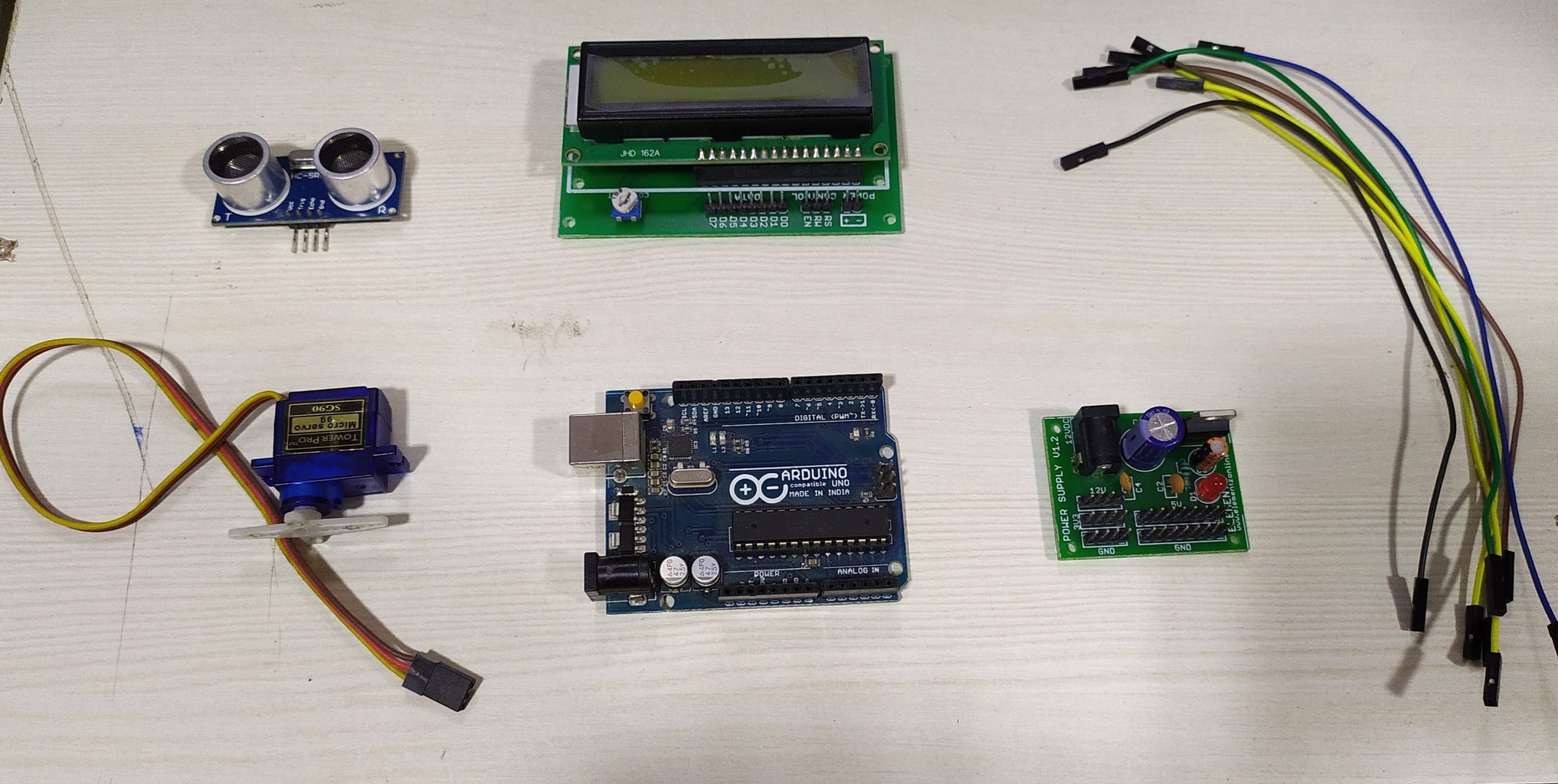
Arduino UNO R3- It is a microcontroller board based on a removable, dual-inline-package (DIP) ATmega328 AVR microcontroller. It has 20 digital input/output pins (of which 6 can be used as PWM outputs and 6 can be used as analog inputs).
HC-SR04 Ultrasonic Sensor -This sensor is a 4 pin module, whose pin names are Vcc (5v), Trigger, Echo and Ground respectively. This sensor is a very popular sensor used in many applications where measuring distance or sensing objects are required. The module has two eyes like projects in the front which forms the Ultrasonic transmitter and Receiver.
Tower Pro SG90 Micro Servo Motor-This servo is 180° rotation servo. It is a Digital Servo Motor which receives and processes PWM signal faster and better. It equips sophisticated internal circuitry that provides good torque, holding power, and faster updates in response to external forces.It consists of three wires coloured as brown,red and yellow.
Brown/Black: Connected to Ground
Red: Connected to VCC (5v)
Yellow/White: Connected to data pin through this pwm signal is given to drive the motor.
16x2 LCD Display (Green BackLight)- 16x2 LCD display is an alphanumeric display. It is based on the HD44780 display controller, and ready to interface with most microcontrollers. It works on 5V and has a Green Backlight which can be switched on and off as desired. The contrast of the screen can also be controlled by varying the voltage at the contrast control pin(Pin 3).
12v Power Suppli Board
Jumper Wires
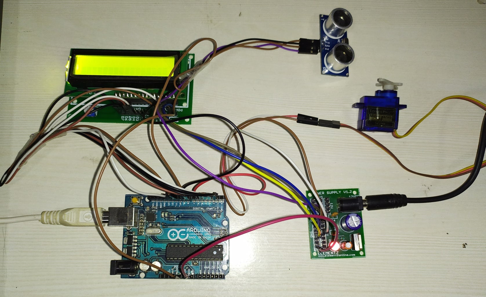
Step 2: Components Connected Together

LCD PIN_RS------------------ 12 of Arduino Uno
LCD PIN_RW ------------------ GND
LCD PIN_EN -------------------11 of Arduino Uno
LCD PIN_D0 ------------------- NC
LCD PIN_D1 ------------------- NC
LCD PIN_D2 ------------------- NC
LCD PIN_D3 ------------------- NC
LCD PIN_D4 ------------------- 5 of Arduino Uno
LCD PIN_D5 ------------------- 4 of Arduino Uno
LCD PIN_D6 ------------------- 3 of Arduino Uno
LCD PIN_D7 ------------------- 2 of Arduino Uno
LCD PIN_VSS------------------ GND
LCD PIN_VDD------------------ 5V
Sensor Pin_VCC----------------5V
Sensor Pin_Trig------------------8 of Arduino Uno
Sensor Pin_Echo-----------------9 of Arduino Uno
Sensor Pin_GND------------------GND
The servo motor has a female connector with three pins. The Brown/Black one is usually the ground.
Connect the power cable that in all standards should be red to 5V on the Arduino.
Connect the remaining line on the servo connector to a digital pin on the Arduino.
Buzzer pin- Positive is connected to the digital pin of Arduino and other pin is connected to the ground.
Step 3: The Code
Download the main code from the below link:-
Main code : https://github.com/soorajece1993/Ultrasonic-Radar-System-Using-Arduino.git.
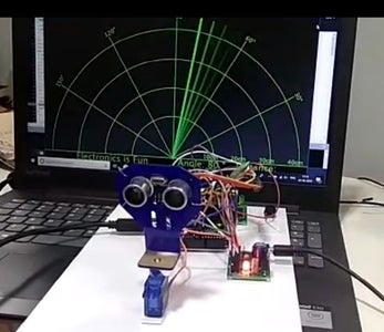
After uploading the program to Arduino, you can see the radar system using a software named 'Processing'.
Processing is available for Linux, Mac OS X, and Windows.
You can download the software from the link: https://processing.org/download/. Select your choice to download the software.
Run the processing code after uploading the main code .
Note:- You have to change the port name and change conditions according to your need.
When you run the processing code, a black window is opened.You can see the moving radar and whenever an obstacle is detected a red line is appeared.
You can download the processing code from the above link (Main code).
Hope this made it easier for you. If you like this instructable and found it useful don't forget to subscribe and if you have any doubts, questions or need help with anything, just leave a comment below…
Thanks elementzonline.com


