

Introduction: Using an Esp8266 Arduino to Control a Relay Using Home-assistant


This Instructable shows how to connect a relay module to an esp8266, something that should be straight forward but needs a few extra components to make the relay work correctly if you're using the small esp device in the pictures.
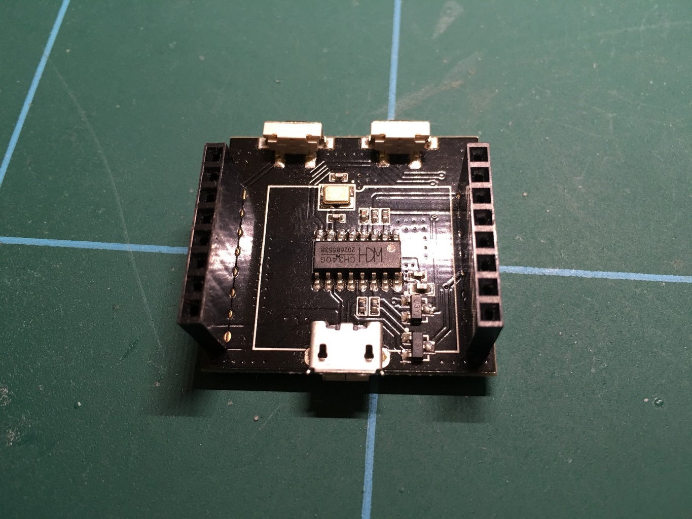
This board was from ebay and has an AMS1117 voltage regulator built onto the board so that you can connect it straight to a USB type power source.
The board also comes with a little daughter board which has a CH340G chip on it which allows you to plug the esp board into it and program it, and once programmed the esp can then be removed and used in a project.
There are upsides and downsides to this form factor which are that once the esp is programmed if you need to change some of your code you need to take it out of your project and plug it back into the programmer. An upside would be that the esp device is smaller than a NodeMCU Devkit, so if you're tight for space this might be a good trade off.
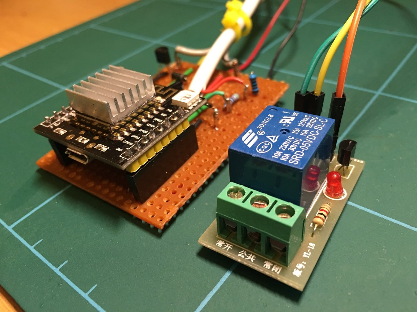
The circuit on the veroboard in these pictures is doing more than just the relay control. More on that in another Instructable later.
Step 1: Things You'll Need


- ESP8266
Arduino relay module
Veroboard
BC547B transistor
1Kohm resistor
1N4001 diode
Some wire, soldering iron, solder etc to actually build the circuit
Step 2: The Circuit

The circuit I used to control the relay with the esp8266 uses a BC547B transistor, a 1K resistor and a 1N4001 diode.
I connected the control wire from GPIO16 on the esp but any of the GPIO pins could be used.
- The emitter of the transistor is connected to Ground along with the GND pin of the relay.
- The base of the transistor is connected to the control pin from the ESP via the 1K resistor.
- The collector of the transistor is connected to the control pin on the relay which is also connected to VCC via the diode.
Its a very simple circuit which switches the control pin of the relay to ground when the GPIO pin goes high.
Step 3: Home-assistant Setup


You can use home-assistant (https://home-assistant.io) to control the relay via the MQTT server and ESP8266. The switch config for home-assistant below will switch on and off the relay using the topic 'ha/switch1'
switch:
platform:
mqtt name: "Switch1"
state_topic: "ha/switch1"
command_topic: "ha/switch1"
qos: 0
payload_on: "ON"
payload_off: "OFF"
optimistic:
false retain: true
Step 4: ESP8266 Sketch

The sketch I've written for the esp8266 also has code for reading the temperature from a DS18b20 and also detecting if the LED is on or off on the control box for my boiler, but I've removed this code for this Instructable and will include it in separate Instructables.
#include <ESP8266WiFi.h>
#include <PubSubClient.h>
// Update these with values suitable for your network. const char* ssid = ""; const char* password = ""; const char* mqtt_server = "";
WiFiClient espClient; PubSubClient client(espClient); int HeatingPin = 16; String switch1; String strTopic; String strPayload;
void setup_wifi() {
delay(10); // We start by connecting to a WiFi network Serial.println(); Serial.print("Connecting to "); Serial.println(ssid);
WiFi.begin(ssid, password);
while (WiFi.status() != WL_CONNECTED) { delay(500); Serial.print("."); }
Serial.println(""); Serial.println("WiFi connected"); Serial.println("IP address: "); Serial.println(WiFi.localIP()); }
void callback(char* topic, byte* payload, unsigned int length) { payload[length] = '\0'; strTopic = String((char*)topic); if(strTopic == "ha/switch1") { switch1 = String((char*)payload); if(switch1 == "ON") { Serial.println("ON"); digitalWrite(HeatingPin, HIGH); } else { Serial.println("OFF"); digitalWrite(HeatingPin, LOW); } } } void reconnect() { // Loop until we're reconnected while (!client.connected()) { Serial.print("Attempting MQTT connection..."); // Attempt to connect if (client.connect("arduinoClient")) { Serial.println("connected"); // Once connected, publish an announcement... client.subscribe("ha/#"); } else { Serial.print("failed, rc="); Serial.print(client.state()); Serial.println(" try again in 5 seconds"); // Wait 5 seconds before retrying delay(5000); } } } void setup() { Serial.begin(115200); setup_wifi(); client.setServer(mqtt_server, 1883); client.setCallback(callback);
pinMode(HeatingPin, OUTPUT); digitalWrite(HeatingPin, HIGH); } void loop() { if (!client.connected()) { reconnect(); } client.loop(); }
This sketch will switch the relay on and off when ever the MQTT broker receives a message of 'ON' and 'OFF' to the topic of 'ha/switch1'.
You can change this how ever you want in the sketch, as long as you also change the home-assistant switch config too in Step 3.
