

Introduction: Using an ACS712 and Arduino to Detect Actuator Limits


I'm working on a project that uses a 400lb force, 30" throw actuator that has built-in, unmovable limit switches but doesn't provide positioning feedback. Most of the (affordable) large actuators I found do not provide feedback and have just two wires - the DC Motor A & B.
The object being moved is mechanically engineered to work at the 30" range, so I mostly just need to know when the actuator is fully extended or retracted. Unfortunately, mechanical switches would be hard to mount on this - I would probably have to design a 3d printed collar w/switch for the top of the actuator and embed a switch at the top of the rail track, or .... I suppose knowing the time it takes to move the full range you could 'guess' that you were fully extended/retracted. Or....
Since the actuator has built in limit switches that stop the motor when at either of the unmovable limits, what if you could just detect when you think the motor should be moving but isn't?
Using an ACS712 current sensor module like those available here, for under $5 seems like it should work and it does!
Step 1: Go Shopping!
You will need the following:
- An ACS712 Current Sensor Module like the ones here. They come in 5A, 20A and 30A models. Since the actuator used for the example has a 10A max drain, we need a 20A.
- A 2 wire ("for convenience" :/) actuator - like this one I'm using. Note that the max amperage of the actuator should be less than or equal to the amperage of your ACS712 module, motor shield, and the 12V power supply used. For this example, the actuator is rated 10A@12V
- An Arduino - I'm using an Uno in the example.
- A DC motor shield or breakout board that uses PWM. Again, important to have one that supports at least the amperage of your actuator. For the example, I'm using the SHIELD-MD10 R2 from Cytron Tech which is a 10A single motor driver. It's a little pricey at $19USD but take care with the cheaper options that they support the voltage and amperage needed. Note that bidirectional support is neccessary, but PWM support is not for limit detection. In fact, to sample a stable current, the motor must be run at full speed. If you are using a motor controller or shield that only has on and off, not PWM, replace the calls to analogWrite with digitalWrite in the sample source.
- A power supply; voltage should be greater than or equal to actuator and motor controller spec vin. For this example I'm using my old RadioShack (soo vintage!) 25A@13.8V switching power supply. Even though the actuator only says 12V in, most 12V motors and circuits will handle up to 14V (because a 12V battery charges at that voltage).
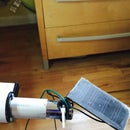
Step 2: Wire It Up!

I think the picture kinda says it all?
Note that the positive line from the power supply flows through the ACS712 from left to right when looking at front of module. If you reverse the flow you will see a value on the analog input equivalent to not having anything connected to the pin.
Step 3: Test the ACS712
The motor shield that I'm using isolates the power for the motor from the Arduino. It's a good thing because motors make a lot of noise, but it means that you will need to power the Arduino separately. Optionally you could power the Arduino off of the same 12Vin and add a diode and capacitor. For this example, let's just power the Arduino off of the USB.
- 12V power supply should be off
- Go ahead and plug in your USB from Arduino to your computer
- Upload the code that follows instructions
- Open a serial monitor (Tools / Serial Monitor from Arduino IDE)
If every thing is working, you should see readings between 500 - 520. This is right. Due to the way the ACS712 works, the voltage out produced is 1/2 of VCC when no electromagnetic field is present, you should see 1/2 of 1024 or about 512.
Since this sensor works on the hall effect principle, it may fluctuate, you should see a change if you pass a magnet near the sensor. Fun stuff!
/*
analogRead  - reads an analog pin N times per second over N period and
  writes the min and max to the console
*/

#include

#define ANALOG_PIN A5
#define SAMPLE_INTERVAL 10    // every 10ms
#define SAMPLE_PERIOD   1000  // 1 sec

// the setup routine runs once when you press reset:
void setup() {
  // initialize serial communication at 9600 bits per second:
  Serial.begin(9600);
  pinMode(ANALOG_PIN, INPUT);
}

// the loop routine runs over and over again forever:
void loop() {
  int min = 0xff;
  int max = 0;

  for (int i = 0; i < SAMPLE_PERIOD / SAMPLE_INTERVAL; i ++) {
      int sensorValue = analogRead(ANALOG_PIN);
      if (min == 0xff || sensorValue < min) min = sensorValue;
      if (sensorValue > max) max = sensorValue;
      delay(SAMPLE_INTERVAL);
  }
  char out[255];
  sprintf(out, "min=%d max=%d", min, max);
  Serial.println(out);
}
Step 4: Test the Motor and ACS712

With the serial monitor and code from the last step still running, turn on your power supply. You shouldn't see any change in the reading.
The motor controller we are using for the example has little switches to manually move the actuator at full speed. Using the switch to move the motor in either direction should cause the value read from analog input to drop < 490.
There is a good exercise in math for anyone that wants a little extra credit to print out the electrical current in Watts or A@12V. For extra, extra bonus points, tell me how much weight is being moved. The actuator only drains 10A when at full load (400lbs).
Step 5: Let's Calibrate!
So, now all that is left is to apply what we learned from the previous step.
If you upload the code that follows, you should see your actuator come to life and stretch it's legs.
Note that the ACTUATOR_SPEED is constant at 255 (max). You can use this technique and use the variable speed that PWM provides, but you must have the PWM at full speed before sampling the ACS712. If you lower that variable to say 200, you'll see that you occasionally hit readings near rest (512). That is because the controller is not lowering the voltage to lower the speed, but instead pulsing the 12Vin to the DC motor like someone standing at a light switch and turning it on and off over and over. If you sample the current sensor while not at full, you are likely to sample a no current reading falsely.
/*<br>  Every few minutes, move the actuator through it's full range of motion and report time,
  limit detection and other useful diagnostic info

  Tested on Arduino Uno with Cytron MD10 10A motor shield driving a Figerelli 30"/400lb
  actuator.

  The larger actuators have built in limits that stop the motor, but no way of telling
  the controller that the actuator is at it's limit.   Using an ACS712 hall effect sensor
  module connected to the ACTUATOR_AMP_SENSOR_PIN, we detect when the actuator should be
  moving but the motor is not drawing any power.

*/

#define ACTUATOR_AMP_SENSOR_PIN A5
#define ACTUATOR_PWM_PIN 11
#define ACTUATOR_DIR_PIN 12

// MAX speed is 255 - this is the value that gets written to the ACTUATOR_PWM_PIN
#define ACTUATOR_SPEED  255

// when the amp sensor analog value is between these, it is considered to be at rest (no
// current being drawn.
#define ZEROAMP_RANGE_LOW 505
#define ZEROAMP_RANGE_HIGH 520

// limited to 255 char strings
void serialPrintf(char const *format, ...) {
  char buffer[255];
  va_list args;
  va_start(args, format);
  vsprintf(buffer, format, args);
  va_end(args);
  Serial.println(buffer);
}

boolean isActuatorMoving() {
  int val = analogRead(ACTUATOR_AMP_SENSOR_PIN);
  serialPrintf("Amp sensor reading: %d", val);
  return val < ZEROAMP_RANGE_LOW || val > ZEROAMP_RANGE_HIGH;
}

void moveActuator(int direction, int speed=ACTUATOR_SPEED) {
  serialPrintf("moving actuator direction=%d, speed=%d", direction, speed);
  analogWrite(ACTUATOR_PWM_PIN, speed);
  digitalWrite(ACTUATOR_DIR_PIN, direction);
  delay(200);
}

void stopActuator() {
  analogWrite(ACTUATOR_PWM_PIN, 0);
}

// returns the number of milleseconds taken
unsigned long moveActuatorToEnd(int direction) {
  long startMs = millis();
  moveActuator(direction);
  delay(100);
  //while (millis() - startMs < 2000) {
  //  delay(1);
  //}
  while (isActuatorMoving()){
    delay(300);  // slight delay between sampling the ACS712 module is recommended
  }
  stopActuator();
  long endMs = millis();
  return endMs - startMs;
}

// the setup routine runs once when you press reset:
void setup() {
  // initialize serial communication at 9600 bits per second:
  Serial.begin(9600);

  pinMode(ACTUATOR_PWM_PIN, OUTPUT);
  pinMode(ACTUATOR_DIR_PIN, OUTPUT);
  pinMode(ACTUATOR_AMP_SENSOR_PIN, INPUT);

  serialPrintf("setup complete");
}

// the loop routine runs over and over again forever:
void loop() {
  int currentDirection = 0;

  if (isActuatorMoving()) {
    serialPrintf("FAILURE: sensing movement on actuator when it should not be");
    delay(250);
    return;
  }
  // start at one end it should already be at an end unless the actuator started the loop
  // in the middle.   We could test that it takes less than n time to the first end on
  // second and subsequent iterations of loop()
  moveActuatorToEnd(currentDirection);
  delay(2000);

  for( int i = 0; i < 2; i++ ){
    currentDirection = (currentDirection + 1) % 2;   // 0 -> 1, 1 -> 0
    long ttm = moveActuatorToEnd(currentDirection);
    serialPrintf("moved end to end (%d) in %ldms", currentDirection, ttm);
    delay(1000);
  }
  delay(10000);
}
Step 6: The Big Picture


Here is the end goal. Hope this was helpful,
~bee
