

Introduction: Using the Accelerometer on the Arduino 101


This is the fifteenth module of the series of lesson about use cases of the Arduino 101. Another feature that differentiates the Arduino 101 from the Uno is that the 101 has includes an IMU which includes an accelerometer. In this project, the accelerometer will be used to control motor. As the accelerometer detects a sideways motion it will spin the motor clockwise and and is detects the opposite sideways motion it will spin counterclockwise -- in the opposite direction.
Step 1: Tools and Materials
- Arduino 101
- Breadboard
- SparkFun Motor Driver - https://www.sparkfun.com/products/9457
- DC Motor
- Jumper Wires
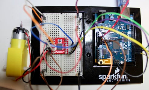
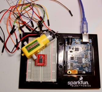
Step 2: Circuitry

The circuitry is the same as connecting a motor to the Arduino. There are many ways of driving a motor using an Arduino, two of which have been covered in past modules, and this will be using a Sparkfun Motor Driver board. However, this project will not require the use of the previous Instructable.
Connecting power from the Arduino power to the breadboard
- We will need two sources, one with 5V and the other at 3.3V, so we will be using both sides of the ground rails of the breadboard in this project.
- As a convention and as an organizational tool, all 5V sources will be marked with red and black jumper wires. While, the 3.3V sources are marked with orange and brown jumper wires.
- Connect the 5V pin from the Arduino to one of the red power rails on the breadboard with a red jumper wire.
- Connect the 3.3V pin from the Arduino to the other red power rail on the breadboard using an orange jumper wire.
- Connect the GND from the Arduino to the 5V black ground rail on the bread board using a black jumper wire.
- Connect the 5V black ground rail to the 3.3V black ground rail using a brown jumper wire. Ground is ground so it doesn't make a difference which ground we use.
When wiring the SparkFun motor driver, it is easiest to follow the wiring diagram for the motor driver since the pin names are on the opposite side facing the breadboard.
- Connect all the power and ground for the board to 3.3V.
- Connect the power and ground designated the motor (on the left side) to 5V.
- Connects pins 4, 5, and 6 from the Arduino to the motor driver board on the breadboard.
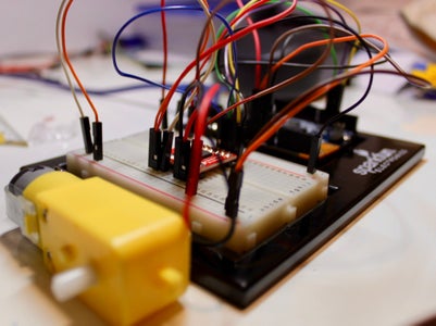
Connecting the motor to the motor driver board.
- Connect the motor pins to the 2nd last and 3rd last pin on the left side of the board. The order does not matter. This will be supplied 5V by the motor driver board.
Step 3: Code
#include "CurieIMU.h"
const int DIR_A = 4; const int DIR_B = 5; const int PWM = 6;
// previous orientation (for comparison). Start at (-1) to start with
void setup() { //set motor control pins to OUTPUT pinMode(DIR_A, OUTPUT); pinMode(DIR_B, OUTPUT); pinMode(PWM, OUTPUT);
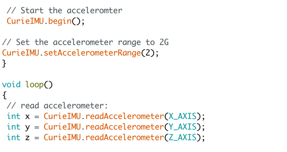
// Start the acceleromter CurieIMU.begin();
// Set the accelerometer range to 2G CurieIMU.setAccelerometerRange(2); }
void loop() { // read accelerometer: int x = CurieIMU.readAccelerometer(X_AXIS); int y = CurieIMU.readAccelerometer(Y_AXIS); int z = CurieIMU.readAccelerometer(Z_AXIS);
// calculate the absolute values, to determine the largest int absX = abs(x); int absY = abs(y); int absZ = abs(z);
if ( (absZ > absX) && (absZ > absY)) { // base orientation on Z if (z > 0) { brake(); } }
//else if Y is greater than X and Z its on edge else if ( (absY > absX) && (absY > absZ)) { // if Y is positive orientation (digital pins up)and is set to 1 if (y > 0) { forward(); } //the Y is in the negative orientation (analog pins up) and is set to 2 else { reverse(); } } } //custom function for driving the motor forward void forward() { digitalWrite(DIR_A, HIGH); digitalWrite(DIR_B, LOW); digitalWrite(PWM, HIGH); }
//custom function for driving the motor in reverse void reverse() { digitalWrite(DIR_A, LOW); digitalWrite(DIR_B, HIGH); digitalWrite(PWM, HIGH); }
//custom function for braking the motor void brake() { digitalWrite(DIR_A, LOW); digitalWrite(DIR_B, LOW); digitalWrite(PWM, LOW); }
Step 4: Demo
The motor will spin one way when the Arduino is tilted left, and spin the opposite direction when tilted in to the right.

Participated in the
Makerspace Contest 2017


