

Introduction: Wheeled Robot Platform


The purpose of this proyect, consist on the development of a simple, easy to assembly and maintain robot base. Also space for the sensors, actuators and electronic will be available inside the platform
Step 1: Sketchs and Drafts

The requirements are: enought space for the electronics, sensors and battery. Assembly should be easy to perform and disassembly also should not require many steps in order to make easier the maitenance works. Two main subsystems will be manufactured, first the robot powertrain and second the base with the switches
Step 2: 3D Modeling

According to the desired characteristics and the firts sketchs, a more realistic moden can be done using a 3D modeling program in order to habe a better idea how it will look. There are many open source programms for 3D modeling available
Step 3: Required Materias


Using the blueprints obtained from the 3D modeling program, the manufacturing and the assembly of the componets can be done. Here I include the list of the required componets:
- Epoxy glue
- Acrylic (1 in)
- Screws and locknuts (1 in)
- Aluminium sheet (1/2 in)
- micro switche
- cable
- 2 position switch
- Motor sed: Motor + reduction + wheel
Step 4: Assembly and Wiring

The acrylic will be cut in order to habe 2 platforms (big one and small one), the 4 columns for the upper platform. These pieces will be joined using the epoxy glue. The powertrain subsystem will be assembled using the motor sed and the aluminum sheet, also the base for the line follower sensor will be manufactured using aluminium.
The required holes will be done and then the 2 subsystems will be assembled. Then the micro switches and the 2-positions switches will be installed and the needed therminals from each component will be wired.
Step 5: Robot Platform Powertrain

For the powertrain it is important to know that the polarity of the motors cannot be instantly changed. That means that when it is required to change the direction of turn of the wheel, it is required to reduce the speed till reaches the value of cero, then start the motor in the opposite direction. This recomendation will reduce the required maintenance in the powertrain system and als will increase the lifecycle of the motor, the reduction and the mechanicas components of this subsystem
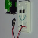
Step 6: Installing and Testing the Additional Components

Now the robot platform is ready to be used and test the components and the planed functionality. The components that can be installed in this platform could be:
- Ultrasonic sensor
- LCD Screen
- Bluetooth module
- Line follower sensors
- 2 protoboards
- 2 development modules wit microcontrolers and also a small protoboard
- Camera module
- Motor shield driver
- Keypad
- Battery


