

Introduction: Wireless Lunar Phase Tracker


The Lunar phase tracker is a small, semi-portable device which allows you to gather critical information about the Moon. The device reports back parameters such as the visible illumination, the phase, moon rise and set times and more.
This device is essential for anyone who has an interest in science or astronomy and provides a great desktop office decoration and is certainly a conversation starter.
The project is fairly simple and requires an internet connected device such as an ESP32 however you can always adapt the code to work with a WiFi shield, Ethernet shield or any other internet connected device you may have. The Lunar Phase Tracker has been designed to work off Lithium-Polymer batteries and a very power efficient E-ink display which not only provides a wonderful screen to look at but also holds the last image even if the power goes off!
Step 1: Registering for Astronomy Information


This step is absolutely essential (although boring) as we are using an online API to gather our information. While it is possible to calculate the moon phases, illumination etc, it is a tedious task to do so. The API we are using provides up-to-date information from live weather station and monitoring systems so the data we receive, is real world results and not that of calculated values.
Head over to Weather Underground, click "sign up" and fill in all your information. The account is totally free and so are your API calls as long as you dont request too many results per minute or exceed 500 requests per day. Make sure you bookmark this page, you can always come back later and use the API for weather statistics and other great information. Once you have created your account, go to the API Site, click on "purchase key" and select the free plan, you simply have to input a few details and you will be issues with a devoloper Key ID. This ID is unique to you and should be kept private. I have provided my key in the example Arduino code which we will look at a bit later. You are more than welcome to use my Key ID for testing purposes but I highly recommend signing up for your own.
Once you have your unique ID, you can head on over to the Astronomy API information, which is honestly very bare. You will find a simple example which looks like this:
http://api.wunderground.com/api/8c6dc2e5c6f36de9/a...
This URL is extremely important as this is what issues us with all the information we need to make our project. Go ahead, click the link, you will see results for Sydney such as moon phase, illumination and other good information. Take a look at the URL, we will see Sydney, Australia and a long code that starts off with "8c6dcwe...". That code is your Key ID which we picked up earlier. Change out that code with your unique ID and see how that works, you should get exactly the same result. Try play around with locations. For myself in South Africa, I use Johannesburg and ZA.
Step 2: Components


So now for the interesting stuff. We will need a few components, not many and none of them are extremely expensive and I have provided Amazon links for the components I used. Keep in mind, if you are good with programming, feel free to use any display or internet device you have available. For my build, I used the following:
- ESP32 Dev Board (Generic)
- Adafruit Power Boost 500
- 5000mAh Lipo Battery Pack
- Stripboard (Protoboard)
You will ofcouse need the basic tools such as:
- Soldering iron
- Solder
- Multimeter
- Calipers
- Drill bit to separate tracks on protoboard
- Wire
- Wire Snips
- Glue (Hot glue will work)
- Laptop with Arduino IDE installed
The only advanced tool you may need is a 3D printer to make the enclosure. If you dont have one, thats fine, make your enclosure out of wood and hand saws or anything you have available. And yes, my 3D printer is old and dusty lol.
Step 3: The Computer Software
Before we can start working on the circuit and programming, we will firstly need the most recent version of the Arduino IDE which can be found here.
Since we are using the ESP32 with Arduino core, we will need to install this core on the Arduino IDE. Follow this simple guide from Github which shows you what software and configuration you will need to do so you can use your ESP32 dev board within the Arduino IDE.
We will also need two extra libraries to get our system working. The first is an Arduino JSON library which allows us to read and parse JSON requests which is exactly what we get from Weather Underground. You can download these two libraries from my personal Dropbox or down below. Once you have the files, extract them and place it in your Arduino library folder. Its generally located at C:\Users\YOUR_NAME\Documents\Arduino\libraries. Make sure you restart your IDE otherwise Arduino wont pick up the new additions. The main Arduino SRC code is also in that folder. The library also contains a modified version of the sample provided from Waveshare displays. The files have been altered to run on the ESP32 module with their GPIOs and I have implemented a new "font" which contains all the images for the various phases of the moon.
Attachments

Step 4: The Circuit


Okay so the circuit for this is extremely simple and only requires a few components and wires.
The general idea is that we have a Lipo charger circuit, a boost converter to give us 5V and then the ESP32 Dev Kit which drops the voltage to 3.3V. This 3.3V is also used for the Waveshare E-Ink display. Yes, this is slightly inefficient due to boosting then stepping down with a linear regulator but the ESP32 work over a very horrible voltage range. Somewhere around 2.5 - 3.6V. This is not suitable for battery projects especially ones that use lithium polymer cells.
The basic wiring is as follows:
- Boost converter 5V output --> Vin & GND on ESP32 Dev Kit
- ESP32 3.3V --> 3.3V & GND E-Ink Display
- ESP32 PIN 18 --> CLK E-Ink Display
- ESP32 PIN 23 --> DIN/MOSI E-Ink Display
- ESP32 PIN 5 --> CS/SS E-Ink Display
- ESP32 PIN 32 --> DC E-Ink Display
- ESP32 PIN 33 -->RST E-Ink Display
- ESP32 PIN34--> BUSY E-Ink Display
You can see the wiring is very simple and my DIY boards only took about 15 minutes to construct.Make sure to check for short circuits with a multimeter before providing power.
I also removed the LED's from my ESP32 and Lipo boost board to save about 40mA of power during sleep mode. This will help the batteries last a bit longer. You can implement a power switch, power saving circuit, auto disconnect etc if you wish to. You can expand this project and make it as complex as you want.
Step 5: The Code


The code can be found in the supplied folder during step 3 or you can download the .ino file from down below. You will need to install the associated libraries as mentioned in step 3 to get everything working together. There is not much to say for this step as the code is supplied in a working condition. Make sure to put your SSID and network password before testing the program, you can always run the ESP32 WiFi Scan to detect any nearby wireless networks however in my program, the network information is set in code and code only. Maybe you can modify it to ask what network you want to connect to :)
The code is fairly simple and I will spend some time commenting and refining it in the next few weeks. We basically connect to a network, in my case, my home network. We then attempt to connect to Weather Underground and receive the JSON text from the webpage. The ArduinoJSON library is then used to extract. or parse, the JSON code into char arrays or strings which allow us to manipulate the values before displaying it to the user. The last bit of code is strictly for programming the GUI and was done by trial and error. I looked at the display, incremented or decremented an assets position and ran the code again until I was happy with how the font size, layout and images looked.
I implemented a deep sleep routine for the ESP32 to save power. The default is 60 seconds however I suggest you change the value to something like an hour or two since updates dont occur for at least a few hours. The example accepts seconds so make sure you do the conversions properly.
I also used The Dot Factory program to generate hex arrays for a new font. This font is used to generate the "images" for the moon phases. If you would like to edit the fonts file then make sure you use the above mentioned program for generation. It is a bit confusing since the E-Ink library isnt documented well and most of my success was thanks to trial and error. When I spend more time with this code, I will update the Instructable to provide more information on my findings.
The font used for the moon phases must be done according to a standard ASCII layout. If you open font24 in the EPD-master folder, you can see the layout where the 1st graphic is identified by a white space, the second is an "!" (exclamation sign) and so on. You will see that I pull the associated font using number 3 or a hashtag symbol in the last bit of code (function getLunarChar). This is because Arduino expects the ASCII standard from 32 up to 127. Because we are using fonts that have nothing to do with actual fonts and rather a moon phase graphic matrix, we need to ensure that the ASCII character references our chosen moon phase image. This means that using an ! sign, our lunar phase font shows us the second moon phase graphic in that list. If you look at the lunar phase font, you will see a whole bunch of moon phases, all with different illumination levels. In future I will add more code to make use of all the graphics we have implemented. At the moment we are only using a few however the graphics are already implemented in the lunar phase font and just need to be implemented in the code to make use of it.
Attachments
Step 6: Final Assembly

The last part of the build and the most satisfying, is the assembly process. I designed and 3D printed an enclosure which fits my board. The project is very DIY, there are no professional PCB's or a single standard layout. For the most part, the box i used is large enough to accommodate any lipo charger or boost converter you choose to use. As long as they provide the same basic functionality mentioned in this Instructable then you should be fine.
I used 4 screws to hold the top and bottom half of the enclosure together and hot glue for mounting my DIY circuitry. i used some very small drops of glue to hold the battery in but if I had more time, i wouldve made a custom bracket for all the electronics.
I did also decide to make a hole for a latching push button on the back. This disconnects the battery from the boost converter which is useful if you dont plan on running the device 24/7. Unfortunately the boost converter does still use power even if your ESP32 is in deep sleep mode.
Overall I am very pleased with the outcome. I learnt a lot while using the ESP32 and can see myself using it for a variety of projects in the future.
If you have any questions, feel free to ask, i will be more than willing to help out and if you find any errors in this Instructable then please let me know.
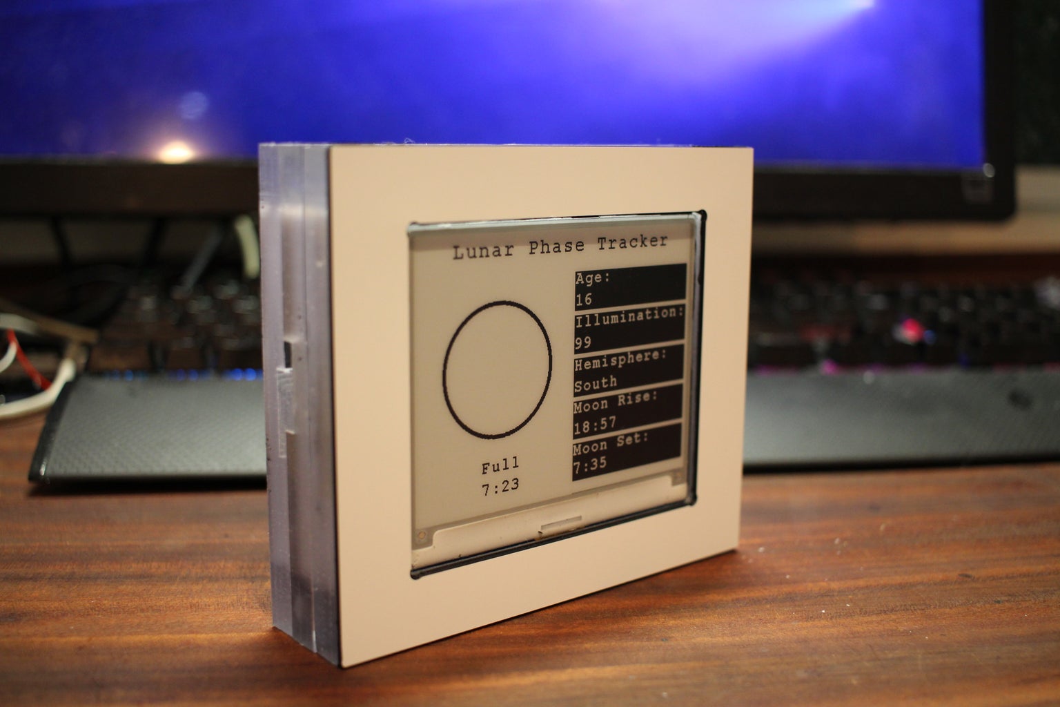
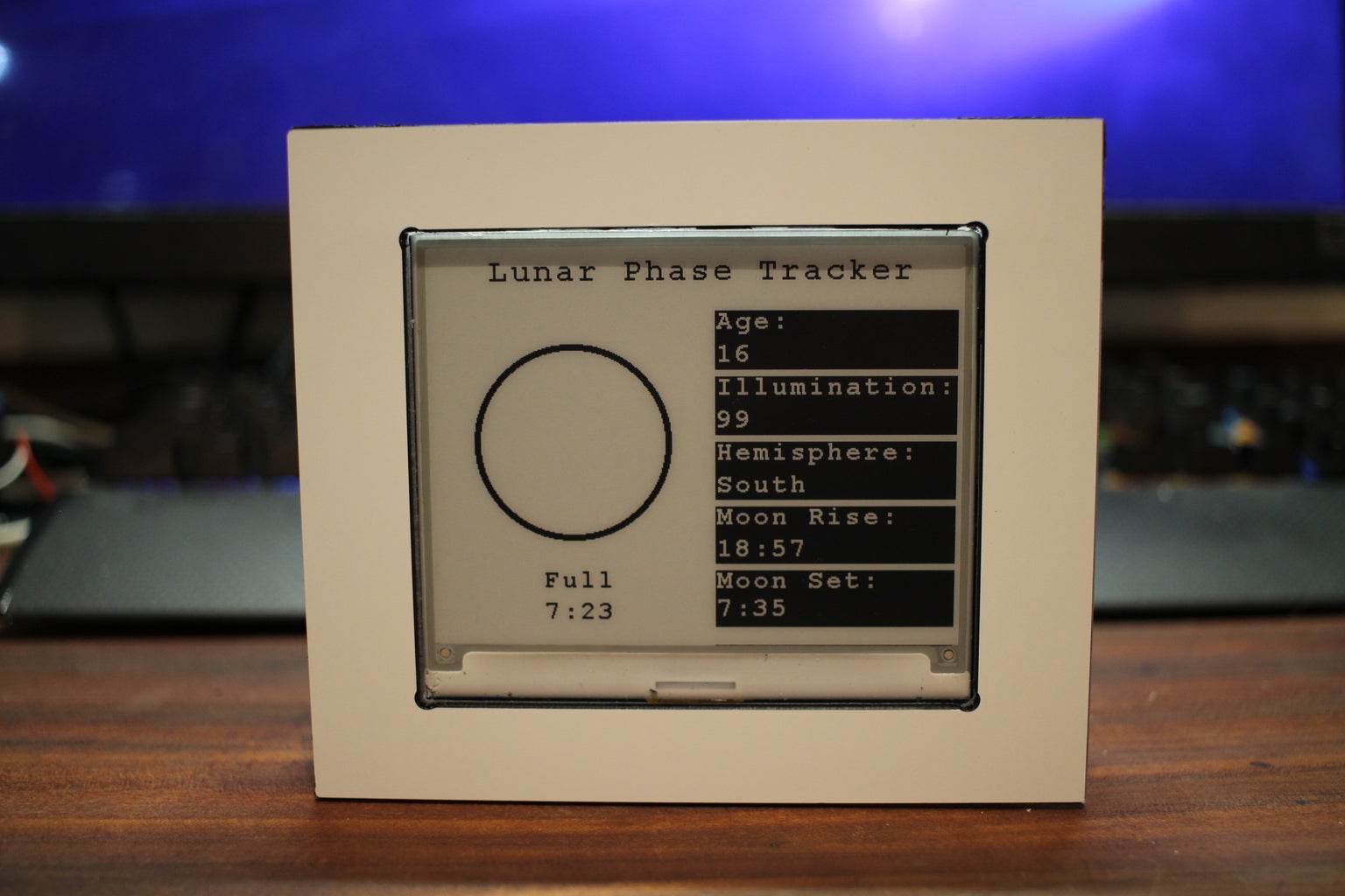
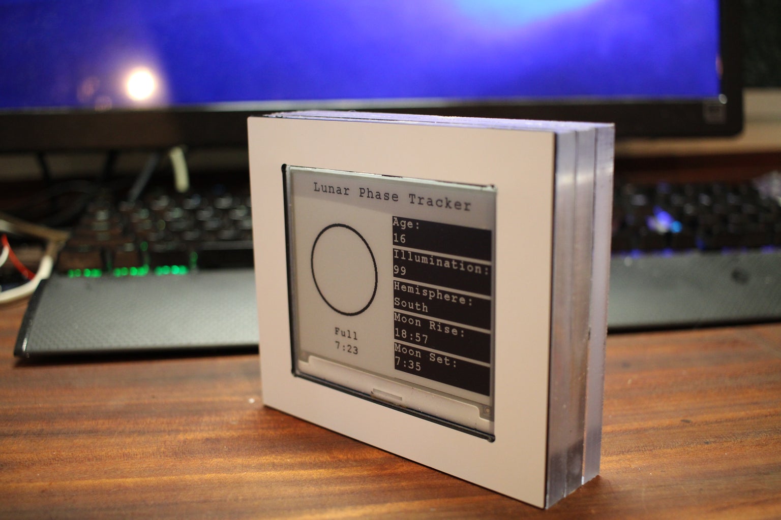
EDIT: I did actually CNC machine a small case instead of the 3D printed version which is what you see in the featured images.
EDIT: In the featured images we see a full moon with 99% illumination. Hence the white circle, as the moon goes through its typical phases, the image of the moon will change accordingly. Further images will be uploaded as the moon progresses through its phases so you can get a representation of the graphics.

Runner Up in the
Space Challenge

Participated in the
Microcontroller Contest

Participated in the
Pocket-Sized Contest


