

Introduction: Wiring Your First 150g Antweight Robot


An Antweight robot is a small, remote-controlled, fighting robot. Like those seen on Robot Wars and Battlebots, but much smaller!
It is one of many weight classes, and the classes may differ based on which country you are in.
In the UK, an Antweight:
- weighs no more than 150g
- fits inside a 4" cube
In the USA, robots this small are known as Fairyweights, and an Antweight is larger.
There is a set of standard rules that most events conform to, so to make sure that you are able to compete with your new robot, have a read through the current ruleset.
This guide will help you to choose the components for, and wire up, the drive system for your first Antweight robot. It does not cover weapons or designing your chassis and armour.
Tools
- Soldering iron + stand & sponge
- Solder
- Protective surface
- Wire cutters & strippers
Components
Step 1: Radio Transmitter & Receiver

Modern radio transmitters use a frequency of 2.4GHz. You pair, or bind, a receiver to your transmitter, and the chances of interference from other systems is low.
You must choose a receiver that uses the same protocol as your transmitter. For example, Spectrum transmitters use DSM2 or DSMX and a FrSky transmitter needs a FrSky compatible receiver.
You should also choose a receiver that supports PWM, or is designed to work with servos. This means that your ESC (see next section) will be able to understand the information it is sending.
This tutorial uses a Spectrum DX5e transmitter, with an OrangeRx R410X receiver, however the techniques discussed will be transferable to other systems.
Step 2: Electronic Speed Controller (ESC)

An ESC is what translates the information sent from your transmitter into information the motors can understand.
They come pre-programmed, and the channels may be mixed or unmixed.
- Mixed: when you push the stick on your transmitter, it can control two motors at once.
- Unmixed: each motor will use a different stick to control it by default, and you can set the mixing on your transmitter.
Which you choose is down to preference, and which radio system you have.
I use unmixed ESCs, because I use a FrSky Taranis X9D+ radio transmitter, which gives me detailed control over the mixing. The Spectrum DX5e in this tutorial has limited mixing options, so using an ESC with mixing would probably be preferable.
Choose a 2-channel bi-directional ESC.
- 2-channel: it can control two motors. Otherwise, you will need two ESCs, one for each motor.
- Bi-directional: it can control each motor in both the forward and backward direction.
ESCs made for planes often only work in a single direction, which is not very useful for antweights!
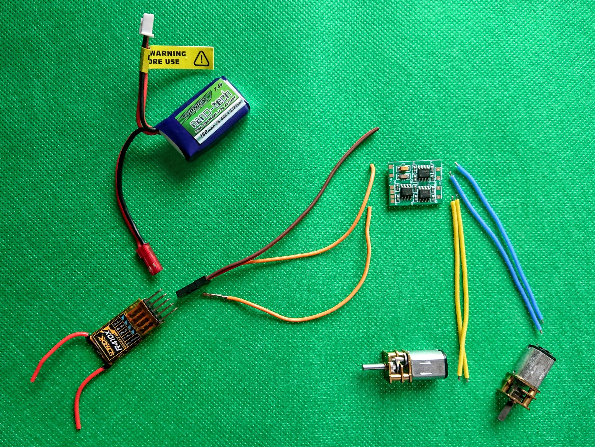
This tutorial uses a DasMikro 2S6A without mixing, however the techniques discussed will be transferable.
- I use DasMikros because they are cheap, not because they are good! There are many better options if you can get hold of them, such as the NanoTwo or the AWESC.
- In a pinch, you can use circuit boards taken out of standard servos. These need modification and are single channel, so save this for emergencies!
Step 3: Batteries

The batteries used in most modern antweights are Lithium Polymer (LiPo) batteries.
They are very light for the amount of power you can get out of them, however they have some downsides.
LiPos are very volatile, and it is important to take care of them, and to charge them using an appropriate charger.
A 2S (two cell) battery will give you around 7.2V, which is plenty for an antweight's drive system.
Do check that your ESC will cope with this voltage.
This tutorial uses a Turnigy nano-tech 180mAh 2S 40C battery, which provides plenty of current, and is a good size.
These are no longer in production. You can get higher discharge batteries, or smaller sized ones, but I have been happy with the performance of these batteries for my own robots so they are good starting point.
To read more about LiPo safety, and understand what all the numbers mean, I recommend this guide.
Step 4: Motors

N20 motors are small, light and reliable.
You can buy them from reputable suppliers, or cheaply from eBay or AliExpress.
The more reputable the supplier, the more likely that the motors will conform to the given specification, however I have had no problems with cheap motors.
To match your 2S LiPo battery, get 6V motors. If you buy e.g. 12V motors, they will turn very slowly; 3V motors might burn out at this voltage.
I use motors geared to an RPM of 300-500, which gives a reasonable but controllable speed.
The speed of your robot is determined by more than just the RPM of the motors however, you must also take into account the size of your wheels and the voltage of your battery.
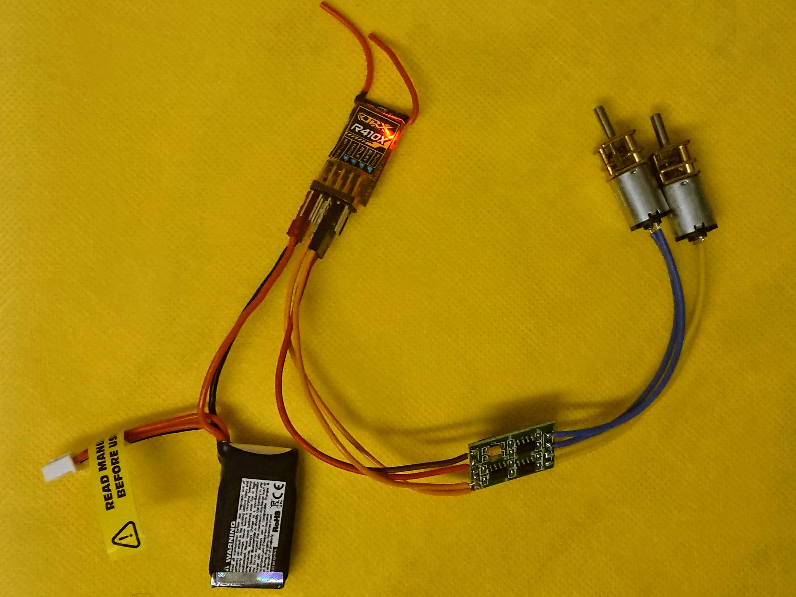
Step 5: Wiring

Now you have chosen all of your components, you can wire them together.
Step 6: Binding Your Receiver to Your Transmitter
If your transmitter allows you to save multiple models, create a new one. Each model can bind to a different receiver, allowing you to control multiple robots from the same transmitter.
The DX5e does not have this option, so I am skipping this step.
Different receivers have different binding instructions, so the first step is to check the manual!
Search online for your receiver. The manual for the R410X is here.
Find the binding instructions in the manual, and follow them.
For the R410X, the first two instructions in the Binding Procedure section say to:
- install a bind plug
- connect power.
On the receiver, is a label BATT/BIND. A bind plug should have come with your receiver. Push this into the labelled column of pins.
Further down in the manual, just above the Channel Connector Description is a picture highlighting which are the signal, power and ground pins on the receiver.
It is important to plug the battery in the correct way around, so the positive lead connects to VCC (the middle pin), and the negative lead connects to GND.
It does not matter which of the positive and ground pins you connect the battery to, as they are all connected together.
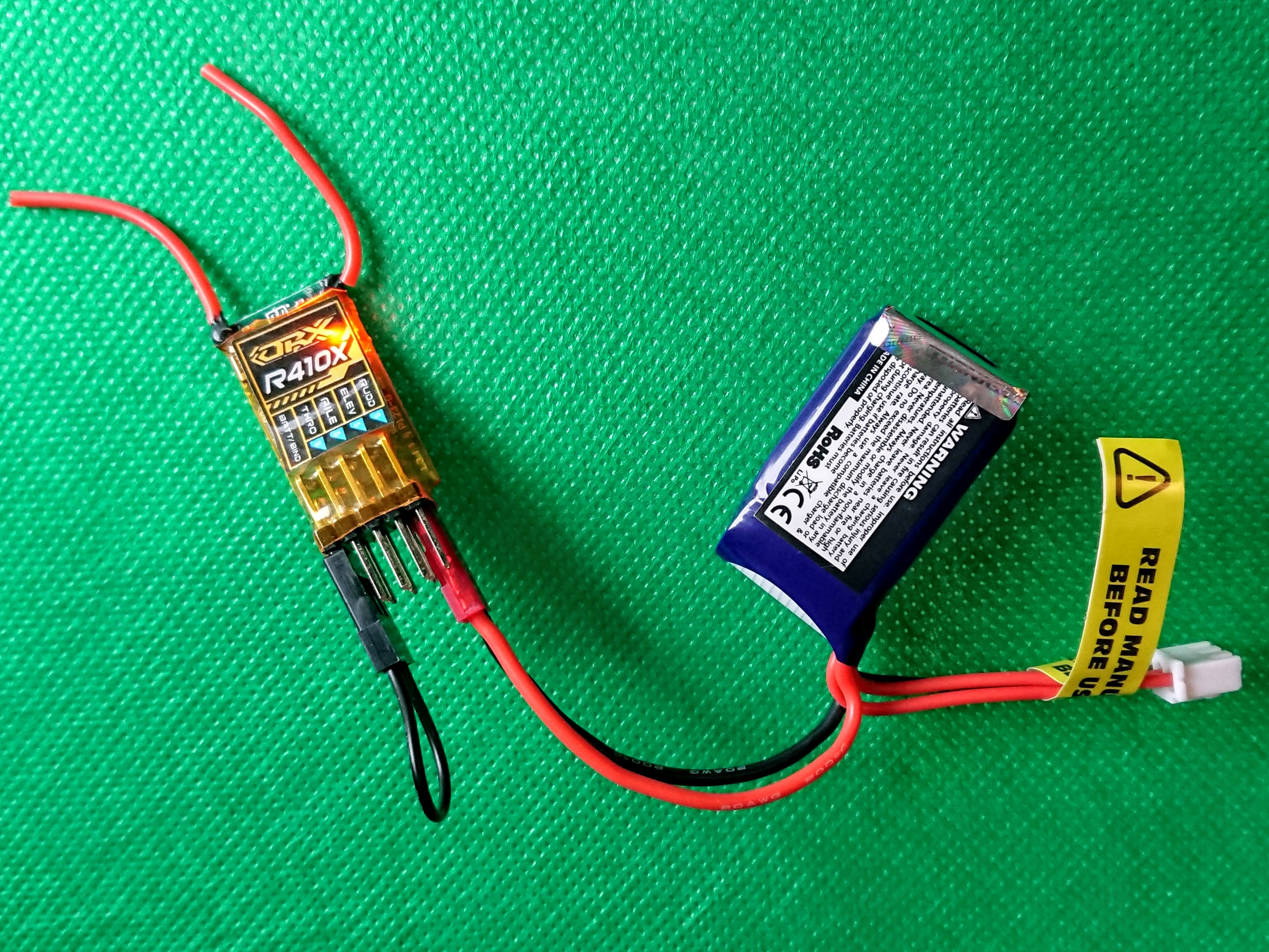
The LED on the receiver should be flashing, which means it is in bind mode.
The next step in the instructions tell us to follow our transmitter's procedure for binding, so we need to find another manual!
The Quick Start Guide for the Spectrum Dx5e is here.
Under the Bind Receiver instructions, step C tells us to move the sticks to the desired failsafe position.
This means what you want your robot to do if the signal is lost - you want it to stop moving and turn off any weapons.
I am going to be using the right stick to drive the robot in these instructions, so make sure that it is settled in the middle and don't worry too much about the others. You can re-bind the receiver later if you want to reset the failsafe.
The trainer switch mentioned in step D is on the top left of the transmitter. Hold it in the forward position while you turn on the transmitter.
The receiver's LED should stop flashing, which means it is connected. If this doesn't happen, repeat the process, and try any troubleshooting ideas given in the manual.
Step 7: Powering Your ESC & Receiver
Find the wiring instructions for your ESC. The Das Mikro instructions are here.
Scroll down to the Wire Connection diagram.
- GND & VCC = battery power, full voltage
- GND & VCC(SERVO,5V/1A) = battery power, regulated down to 5V
- Signal 1 & 2 = connections to the receiver
- Motor A & B = connections to the motors
I am going to detail two ways of adding power to the system, and explain why you might choose each option.
Option A
Plugging the battery into the receiver, and powering the ESC (and therefore the motors) through that.
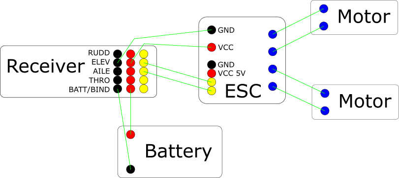
This works if all of your components need the same voltage.
- 2S LiPo = 6-8.4V
- Receiver = 3.7-9.6V
- ESC = 4.2V-9.6V
Nothing will be damaged by the voltage.
Option B
Plugging the battery into the ESC, and powering the receiver through that.
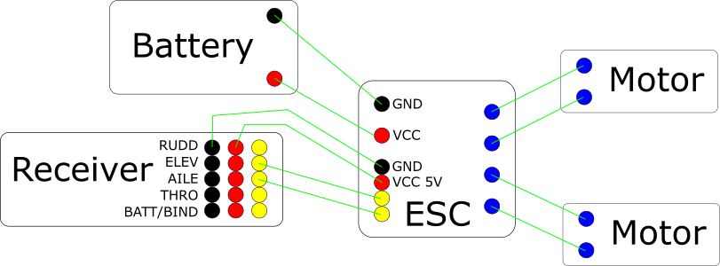
This ESC has the ability to regulate the voltage - to provide a 5V supply to other components.
This is sometimes known as a battery elimination circuit (BEC).
This is necessary if your receiver, or other components being powered from the receiver, need less voltage.
- 2S LiPo = 6-8.4V
- Receiver = 5V
- ESC = 4.2-9.6V
In this case, plugging the battery into the receiver would damage it.
You can get power to your components in a number of ways, these are only two examples (involving as little wiring as possible!)
The important thing is to check the requirements and limitations of your components, to make sure everything is getting the power it needs.
Step 8: Finishing the Circuit
I am going to use the Option A wiring for this tutorial.
As well as power, you need signal wires to that the receiver can communicate with the ESC, and the ESC can communicate with the motors.
The R410X has the following labels:
- RUDD
- ELEV
- AILE
- THRO
- BATT/BIND
These terms refer to flying a model plane, and let you know which channel each signal is connected to.
Some transmitters let you choose how each channel is controlled (and some receivers are labelled channel 1 etc.), however the DX5e does not, so we want to connect the ESC to the channels we need.
This transmitter is a Mode 2, which means that the rudder and throttle are controlled by the left stick, aileron and elevator by the right. Check whether yours is Mode 1 or 2, to see which channels are controlled by which stick!
I want to control both motors from the right stick, which means connecting the two signal wires on the ESC to ELEV and AILE.
Finally, the motors themselves need to be connected to the ESC.
Connect one motor to the Motor A connections and the other motor to the Motor B connections.
If you are using the Das Mikro ESC, you will need to solder wires to the board directly. Other ESCs come with wires attached, so you can plug straight into your receiver.
Connect all of your wires, and secure your motors (e.g. taping them to a piece of strong cardboard) before moving on to the next section.
Step 9: Adjusting Channel Settings

It is unlikely that your motors will move exactly as you want them to when they are first connected. You can adjust settings on your transmitter to get the desired behaviour.
Each transmitter will be different, so check the manual for yours.
Trim
Your motors might be moving, even though you are not pushing the sticks.
You can use the trim buttons to adjust the centre - telling your motors what to do when the stick is centred.
The vertical button controls the aileron, and the horizontal the elevator. Check which motor you have connected to which channel, and adjust the trim until both motors are still.
Mix
One motor is connected to the aileron channel, and the other to the elevator channel.
This means that, if you are using an ESC without mixing, pushing up and down on the right stick will move one motor, pushing left and right will move the other.
This will lead to some weird driving, so you should mix the channels, meaning that pushing up and down on the right stick will move both motors instead.
On the DX5e, this is controlled with a toggle - just push it one way to turn on mixing, the other way to turn it off again.
Reverse
Which direction your motors turn in, depends on which way around they were wired.
You might find that when one motor moves forward, the other moves backward. Or that they both turn backward when you want to go forward.
On the DX5e, there is a toggle switch for each channel, to reverse the direction.
So, if the motor connected to the aileron channel turns backwards when you push up on the stick, flick the AIL toggle on the transmitter.
Step 10: Next Steps...

Once you have set up your drive system, you are well on your way to having a working antweight robot!
A few things to think about...
- How are you going to build the body?
- How are you going to attach the electronics to it?
- Do you want to add a switch to make it easier to turn on or off?
- What will you use for wheels?
The RobotWars101 forum is a great source of help and inspiration - read build diaries, ask questions and hear about upcoming events in the UK.
Your first robot will not be perfect, but completing it is still a great achievement.
Bring it along to a competition to meet other roboteers and get ideas, inspiration and advice to make your second robot even better!
The photo above was taken at AWS59, and shows a wide variety of designs!

Participated in the
Make it Move


