

Introduction: Make Your Own In-circuit Programming Board for the Pickit 3


Now, all the cool kids on the block go on and on about Arduino. Arduino this and Arduino that, but there are other alternatives - sometimes faster, more solid, more controllable analog channels, and definitely more sexy options when you are deciding the suit, vest and tie. Plus, who wants to go mainstream, right?
Enter stage left the PIC.
Having the chops to bypass other's bootloaders and such can give you other assets, in the long run. Yes, there is an initial upfront cost in heave-ho to this, but isn't that what DYI really means...?
I drafted, experimented, and finally produced this at Techshop!
Step 1: Set Up a Regulated De-coupled Power Supply


Dont mess with volts, I tell you. You will never win. And in this case, we need to get from the 9, the battery, all the way down to 3.3 or so. Just look at the data sheet (page 1) which says our 24F16 chip can't tolerate more than 3.8 volts.
So lets bring in a 1117 3.3 voltage regulator.
IMPORTANT NOTE; do not mix up the pin labels in the schematic with that of the actual physical pins! things will get too hot too soon... this is all in the data sheet for the LM117.
Pin 1 goes to ground
Pin 2 supplies the whole board with 3.3 volts.
Pin 3 is the raw 9 volts coming from the battery.
This is great but we need to smooth it out, since any spikes of power could create havoc. We do this by using capacitors to keep the Current Continuously Consistent. The three big C's. Thats what decoupling essentially boils down to (at least for us).
With this pair, we get a smooth sail throughout the whole board. With this setup, I found a 10uF cap on power in and power out pins works wonders. Now these are polarized, so make sure the back strip leg always heads towards ground.
Now its time to check the current supply for the whole board. If there are any issues, best we work them out before adding (and, perhaps, frying) our microcontroller. The reading should be somewhere around 3.3 volts.
Step 2: Add a Switch


I picked up one of those rocket switches from Radioshak a while back. it has an LED included, so theres no need to add one to the board in order to see power on/off.
In this case, connections go from the load to the outcome if switched on, and the third goes to ground (for the included LED). In the image, the green wire is coming from the battery load, and the red is going straight into the voltage regulator, which eventually powers the board.
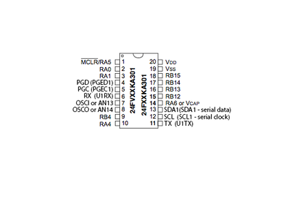
Step 3: Adding the Chip

Now The Brain enters the fray...
Make sure you have the chip the right way up - the dimple on the chip indicates fashion-forward.
Firstly, add the power and ground, as indicated on the datasheets. Speaking of datasheets, they really are a treasure trove. They certainly don't look like it, but how many times in your own experiences does that also ring true, huh?!
Huh? ....
The trick to a datasheet is finding out very quickly what you need from it, in amongst all the other stuff. This can be hard, but then again, so can climbing the fountain in NYC's Central Park (don't ask).
In our case, one of the things we need from it is on page 23. All VDD and VSS pins for the brain must be connected and decoupled (see previous step). In essence, this means they all need to be connected to ground and the board's voltage (this chip can't go over 3.3volts) and all those pairs must have caps (thats what all the pros say, i think, for capacitors?) to smooth out the current. Brains don't like spikes; just think of spikes in terms of a hangover.... As it turns out, our PIC24F16 chip only has one power/ground pair. So lets add a 0.1uF cap between the chips' pins 19 and 20. We should keep these close to the chip, like all good enemies. 0.1uF caps are usually not polarized, so it doesn't matter which leg goes where. Just as long as they both straddle the chip's pins nice and close.
Next, in the datasheet, specifically on page 24, we need look after Pin 1, which happens to be the MCLR, which means Master CLeaR. Embedded engineers really do hate vowels, I know. So, in that page it says adding all these resisters and caps, but I found everything is cool sailing with just a 10k resister going from the MCLR pin to power.
Step 4: Setting Up the Pickit 3


Next, we need to set up the Pickit 3 connections, so we can fling binary between the chip and the Pickit 3. A simple google search brings up the attached diagram - basically we want the MCLR pins on both components to join forces, and each of the pins PGD and PGC also be matched respectively.
pay particular attention to the little triangle on the Picket 3 - that indicates pin 1.
Step 5: Checking the Connection With the MPLAB IPE


Once your chip is hooked up correctly to the Pickit 3, you can check that all is well and right in the world by using the MPLAB IPE.
Now, I haven't touched upon the installation of the latest IDE or IPE for microchip microprocessors. Both are necessary if you want to do all sorts of funky things with your pic chips. But that is for another time. Another place. Another bat channel and, in summary, another Instructable.
But, assuming you have installed all of the above, then you can check your board with the IPE. See the images for clues.
Note also the Caution message image - this happens regularly. Just make sure your chip needs 3.3 volts and you should be good to go.
Step 6: Fff

Participated in the
123D Circuits Contest


