

Introduction: IoT Class: Circuit Displays Internet Data


Congratulations on making it this far! You're through the hardest part of getting up to speed with all of the tools, and now it's time for more fun playtime with data display. In this lesson, we'll build a prototype for a real-time LED weather display. You'll learn to code NeoPixels to light up different colors according to the condition updated from IFTTT by way of Adafruit IO.
Step 1: Simple LED Circuit

Does this circuit look familiar? It should by now! It's the same one we used at the beginning of the previous lesson— a simple pushbutton and LED connected up to the Feather Huzzah ESP8266. Rebuild the circuit according to the diagram and load up the button-to-Adafruit IO test code once more by navigating to File -> Sketchbook -> button_input_led_output. If you can't find it, no worries, just download it from this step (and take better care of this copy, will ya?).

Before uploading the code to your board, fill in your Adafruit IO username and key as well as your wireless network name and password (if you haven't already). Upload the code and test that the button works to illuminate the LED. Use the serial monitor to check if there are any problems (incorrect wifi details would prevent connection, etc.).
int command = data->toInt();

  if (command == 1){ //light up the LED
    Serial.print("received <- ");
    Serial.println(command);
     digitalWrite(LED_PIN, HIGH);
     delay(500);
     digitalWrite(LED_PIN, LOW);
  } else {
    Serial.print("received <- ");
    Serial.println(command);
  }
In this code, the LED does not light up in direct response to the button press, but rather in response to a message being received by the Adafruit IO feed "command". Pressing buttons is only one way to get data into a feed— let's use the IFTTT mobile app to light up the LED instead. If you haven't already, you may wish to switch your previous applet off (the one that sends you email) in your IFTTT settings.

After installing the IFTTT app for Android or iOS, you can complete the applet creation process in your computer's web browser or on your mobile device (the process may have some differences in appearance between platforms but is largely the same).
Click to create a new applet, and pick "Button widget" then "Button press" as the trigger ("+this") and "Adafruit" -> "Send data to Adafruit IO" as the output ("+that").
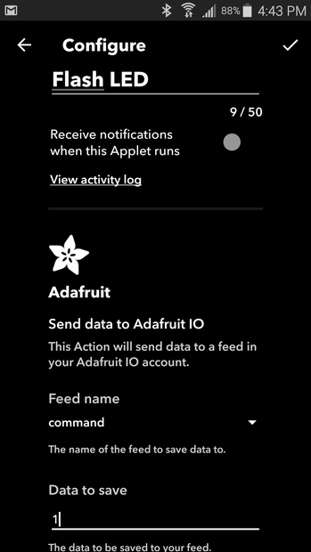
Select your feed "command" from the dropdown menu, and enter the number 1 in the Data field. Click through to finish creating the action.
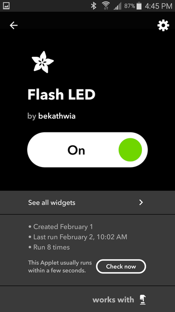
Applets created with the button widget are special— they put a widget on your mobile device that triggers the action with one click of the icon on your home screen. Add your new widget to your home screen using IFTTT's excellent multi-platform guide, and tap away!

What do you notice about the behavior of the circuit? How long does it take for the LED to light up after you activate the widget? When I'm prototyping IoT devices, I will often create a button widget to trigger my circuit manually when it would only otherwise be triggered under certain conditions that complicate prototyping (activities that occur only once per day, only when the weather changes, etc.). It can also be a useful tool in demonstrating a proof of concept prototype where the proposed data source is difficult to simulate live (simulating arriving at a GPS location while inside a presentation hall with wifi but no GPS signal, for example). It's also a great troubleshooting tool.
Step 2: Add NeoPixels
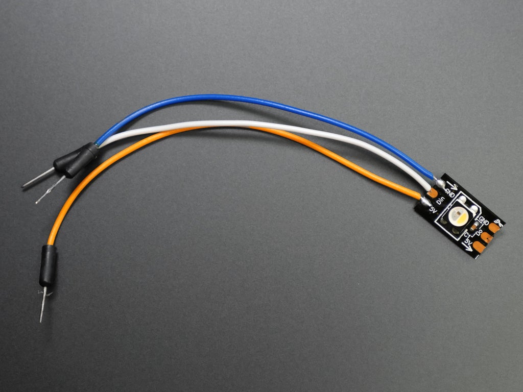
Let's upgrade this circuit's output with some color changing addressable LEDs, aka NeoPixels. You just need one at the minimum, and the sample code later in this lesson uses six. I don't recommend using more than ten pixels for this exercise. If you haven't already, you can learn to solder wires onto your NeoPixels and install the Arduino code library by reading the Skills Infusion lesson in my free Arduino Class. You might find it helpful to resize your browser window so that this lesson is visible along side your Arduino software window.
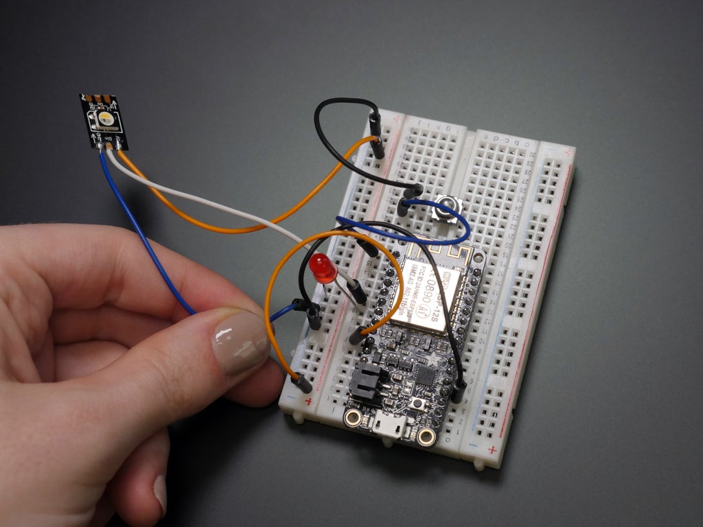
Wire up your NeoPixel(s) to your existing circuit according to the following diagram:

We will add to the button sketch from the last step to make the NeoPixel light up whenever the LED does. Although you can download the example sketch for this step and open it with your Arduino software, I encourage you to try to make the three small code changes by hand, and use the sample file as a fall back and troubleshooting comparison tool. This will flex your coding muscles and hone your eye for details, both of which are essential skills for developing your own projects down the line. I'll walk you through the code changes one at a time, let's go!
Go to File-> Save as... and pick a new name for this modified version of the file. Near the top of the sketch, after the wifi configuration, add in the following NeoPixel setup code, changing the NUM_LEDS variable to match the number of pixels you've got hooked up.
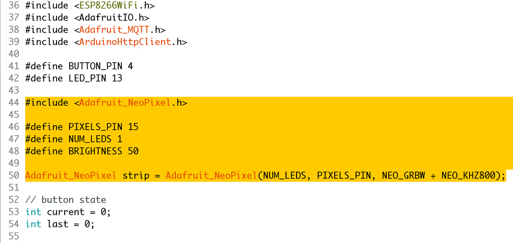
#include <Adafruit_NeoPixel.h>

#define PIXELS_PIN 15
#define NUM_LEDS 6
#define BRIGHTNESS 50

Adafruit_NeoPixel strip = Adafruit_NeoPixel(NUM_LEDS, PIXELS_PIN, NEO_GRBW + NEO_KHZ800);
The first line includes the NeoPixel library, so your program can access its features, the three variable declaration hold the info about where your pixels are plugged in, how many there are, and how bright they should be, and the last light sets up a new NeoPixel object called strip with the features you just described.
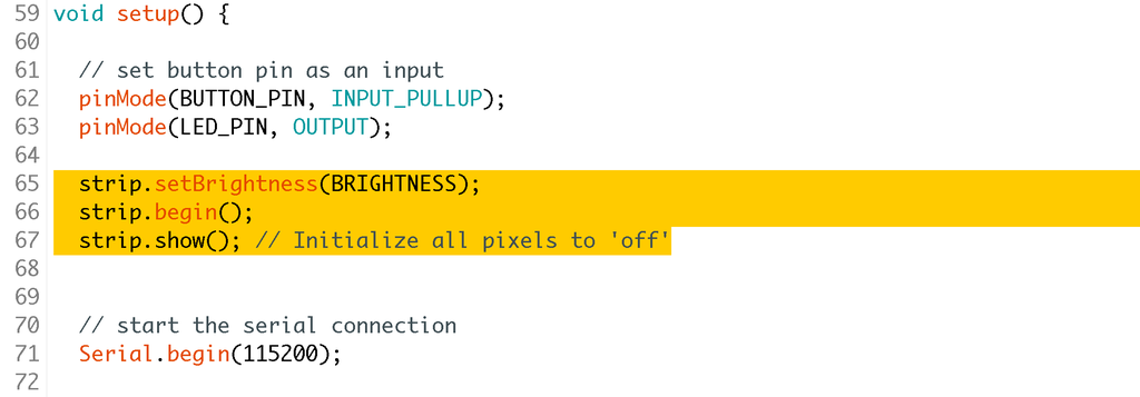
Next, inside the sketch's setup function, add in some lines to activate the NeoPixels:
  strip.setBrightness(BRIGHTNESS);
  strip.begin();
  strip.show(); // Initialize all pixels to 'off'
While setting the global brightness of your NeoPixels isn't mandatory, it can be helpful for prototyping because it conserves a lot of power. A computer's USB port can only deliver about 500mA, so if I'm experimenting with different code and I've got NeoPixels connected, dialing down the brightness makes the circuit easier to power while changing the code frequently. Oh, and it keeps your project from blinding you while you're working on it, too! strip.begin(); and strip.show(); are required to activate the pixel object.
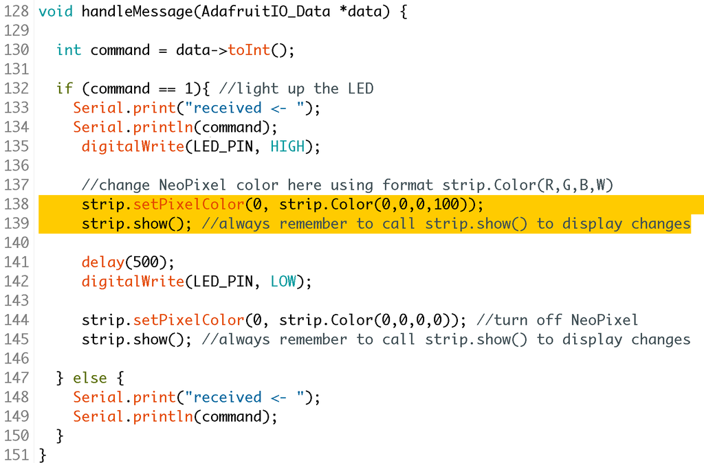
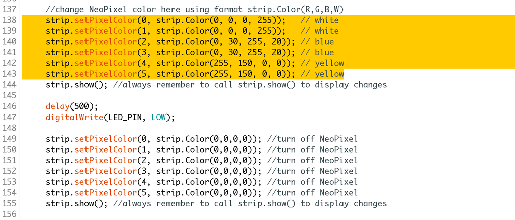
Just below the line of code that illuminates the LED, add two lines that set and show the pixel color change. Customize the color to suit your taste by swapping out the R, G, B, and W values in strip.color();
     //change NeoPixel color here using format strip.Color(R,G,B,W)
     strip.setPixelColor(0, strip.Color(0,0,0,100));
     strip.show(); //always remember to call strip.show() to display changes
Don't forget to add another strip.setPixelColor(); and strip.show(); to turn the pixel off when the LED goes LOW (lines 144 and 145 in the screenshot above).
     strip.setPixelColor(0, strip.Color(0,0,0,0)); //turn off NeoPixel
     strip.show(); //always remember to call strip.show() to display changes
After uploading the updated code, your first pixel should flash along with the LED you connected earlier. At this point you may decide to remove the LED entirely from your breadboard and code, though I like to leave it in place while prototyping/troubleshooting. If you try to compile your code but get errors, comb over your code looking for typos (extra commas, missing semicolons, etc.), and compare to the downloadable sample. If your code uploads but does not light up, check your wifi and AIO details for errors and use the serial monitor to check if your circuit is connecting and receiving data.
To control more pixels, just set their colors with strip.setPixelColor(), each on its own line (and don't forget to double check that the NUM_LEDS variable at the top of the sketch matches your pixel count). Remember to call strip.show(); to display your changes, and turn them all off too.
     strip.setPixelColor(0, strip.Color(0,0,0,0)); //turn off NeoPixel
     strip.setPixelColor(1, strip.Color(0,0,0,0)); //turn off NeoPixel
     strip.setPixelColor(2, strip.Color(0,0,0,0)); //turn off NeoPixel
     strip.setPixelColor(3, strip.Color(0,0,0,0)); //turn off NeoPixel
     strip.setPixelColor(4, strip.Color(0,0,0,0)); //turn off NeoPixel
     strip.setPixelColor(5, strip.Color(0,0,0,0)); //turn off NeoPixel
     strip.show(); //always remember to call strip.show() to display changes
Any time your code has similar repeating element, it's a sign that you can probably make that code more concise. For example, to turn off all the pixels, you could "zero out" the color of each one, on it's own line of code (six pixels shown above), or replace that list with a small for loop:
     for(int i=0; i<strip.numPixels(); i++) { //turn off all NeoPixels
        strip.setPixelColor(i, strip.Color(0,0,0,0));
     }
     strip.show(); //always remember to call strip.show() to display changes
This kind of small code improvement, or optimization, can make your code more flexible and easy to read, and even make the resulting file size smaller. While you may not feel confident enough in your coding skills yet to know when to make these changes, it's important to realize that there are many ways to write code that performs the same actions. In this case either way is fine, but there is one key difference/tradeoff to note: the for loop iterates to strip.numPixels();, which is a built-in function that will return with the number of pixels established at the start. So if you do change the number of pixels later, you'd have less work to do to update the whole sketch to suit.
Next, let's explore another type of data to represent with our pixels.
Step 3: Collect Weather Conditions in Feed
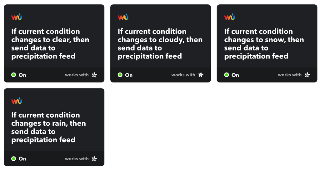
Up until now, our feed's data has consisted only of 0s and 1s. Let's see what happens when we collect some weather data into a new feed called "precipitation". To get an update each time the current weather condition changes, create four IFTTT applets that send data to the same precipitation feed using the Weather Underground trigger, each with a different one of the four condition options. Since this feed is only updated when the weather changes, it can take a few days to see the variation in the data.

Instead of numbers, the feed is filled with words representing a variety of weather conditions. In Arduino, this feed data type is called a String, which is an object that can store multi-character text. You can learn more about this variable type on the official Arduino site, and explore several String examples in the Arduino software. Since we are looking to evaluate the strings in the feed, the StringComparisonOperators example is particularly relevant. In the sample sketch (also accessible in your Arduino software by navigating to File-> Examples->08.Strings->StringComparisonOperators), you can find several if statements with descriptive comments that explain and show how to compare two strings in several different ways.
// two strings not equal (case sensitivity matters):
  stringOne = "This";
  stringTwo = "this";
  if (stringOne != stringTwo) {
    Serial.println(stringOne + " =! " + stringTwo);
  }
  // you can also use equals() to see if two strings are the same:
  if (stringOne.equals(stringTwo)) {
    Serial.println(stringOne + " equals " + stringTwo);
  } else {
    Serial.println(stringOne + " does not equal " + stringTwo);
  }

  // or perhaps you want to ignore case:
  if (stringOne.equalsIgnoreCase(stringTwo)) {
    Serial.println(stringOne + " equals (ignoring case) " + stringTwo);
  } else {
    Serial.println(stringOne + " does not equal (ignoring case) " + stringTwo);
  }
From this section of the example, you can see that comparing strings can be just like comparing numbers by using an if statement and comparison operators == (is equal to) and != (is not equal to), as well as two built-in functions .equals and .equalsIgnoreCase. All three function very similarly, but we'll use .equalsIgnoreCase to provide the maximum input flexibility.
Step 4: Display Weather Data With NeoPixels

Let's start with a new downloadable sample sketch, which does not contain button input, and has been loaded up with the necessary weather handling bits. Open it up in Arduino, personalize it to reflect your wifi and AIO info, and upload the code to your Feather Huzzah NeoPixel circuit. You may leave the pushbutton and LED connected, although they won't be used again until the next lesson.

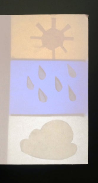
To mock up a weather display, let's make the pixels illuminate some symbols. One of the simplest and best ways to diffuse LEDs is to give them space, so build a small cardboard enclosure that has some depth to it. Add more cardboard walls to divide the pixels into chambers (I'm using three chambers of two pixels each). A piece of plain white printer paper taped to the openings of the chambers provides the "screen," and glueing on another layer of cut paper creates shadowy outlines of whatever shapes you choose.
To test this code, you can manually add data to your feed by clicking on Actions -> Add Data. Type in a weather condition (stick to the ones described in the Arduino sketch) and click Create to add it to the feed. If all's well, your pixels should change whenever the feed updates.
Let's take a look at how the code works so you can customize it for your own projects.
AdafruitIO_Feed *precipitation = io.feed("precipitation"); // set up the 'precipitation' feed
Before the startup function, you'll need to set aside some memory for the feed you'll be using. Though it doesn't have to have the same local name as you call it on Adafruit IO, it sure is helpful in keeping track of everything!
Inside the setup:
  // set up a message handler for the 'precipitation' feed.
  // the handleMessage function (defined below)
  // will be called whenever a message is
  // received from adafruit io.
  precipitation->onMessage(handleMessage);
Pretty much what the comment says— this line calls the function handleMessage whenever the precipitation feed is updated. Scroll down to below the main loop to the handleMessage function, line 101:
String forecast = data->toString(); // store the incoming weather data in a string
This line puts the feed data into a string called "forecast".
  //the following strings store the varous IFTTT weather report words I've discovered so far
  String rain = String("Rain");
  String lightrain = String("Light Rain");
  String rainshower = String ("Rain Shower");
  String AMshowers = String ("AM Showers");

  String rainandsnow = String("Rain and Snow");
  String snow = String("Snow");
  String snowshower = String("Snow Shower");

  String cloudy = String("Cloudy");
  String mostlycloudy = String("Mostly Cloudy");
  String partlycloudy = String("Partly Cloudy");

  String clearsky = String("Clear");
  String fair = String("Fair");
  String sunny = String("Sunny");
These variable declarations describe all the weather conditions I've observed in the feed, grouped loosely by condition. These declarations could be moved to the start of the program, but keeping them here makes it easier to understand the next part with all the if statements:
// if there's rain in the forecast
  if (forecast.equalsIgnoreCase(rain) || forecast.equalsIgnoreCase(lightrain) || forecast.equalsIgnoreCase(rainshower) || forecast.equalsIgnoreCase(AMshowers)){
    Serial.println("precipitation in the forecast today");
    strip.setPixelColor(0, strip.Color(0, 0, 0, 255));
    strip.setPixelColor(1, strip.Color(0, 0, 0, 255));
    strip.setPixelColor(2, strip.Color(0, 30, 150, 150));
    strip.setPixelColor(3, strip.Color(0, 30, 150, 150));
  }
This statement compares the feed data stored in the forecast string against the rainy terms we defined moments ago. Using the or|| comparison operator lets us add multiple conditions to the same if statement, grouping several rainy conditions into the same blue and white NeoPixel output.
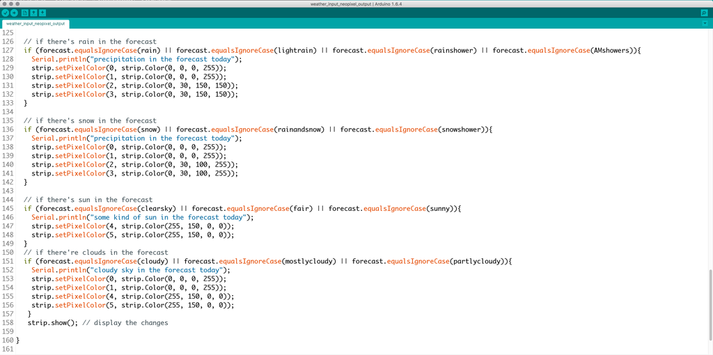
Three more similar if statements evaluate for the three other groups: snow, cloudy, and clear sky. Don't forget to call strip.show(); to display the color changes!

Step 5: Taking It Further

If you find the weather display ideas intriguing and/or useful, you may wish to build a more finalized version with a soldered circuit inside an enclosure of some kind.

You may wish to add a numeric LED display to show the temperature too— find techniques for both in my WiFi Weather Display Instructable!

Perhaps you're interested in visualizing some numerical data like the number of YouTube subscribers— I've got you covered there too. These are just two examples of projects that display internet data, check out more project ideas in the collection below! To complete this lesson, post up a picture of your circuit from this lesson, or a sketch and description of a project you'd build with the skills you learned here. Next up we'll combine inputs and outputs to create two devices that can talk to one another from anywhere there's a wifi connection.
Internet of Things Class table of contents:


