

Introduction: IoT Class: Circuit Triggers Internet Action


Now is a good time to brainstorm a list of IoT projects you want to make. I have a hunch that many of them would involve a physical circuit sending a simple message. You might want an alert when the water heater's leaking, or when a particular door is opened. In this lesson, we'll build a basic project that triggers an internet action when a physical switch is activated.
The code will detect the switch and send a message to a feed on the cloud data site Adafruit IO. Another cloud services site, IFTTT, will monitor this feed and send an email when activity is detected (account setup is covered in the Software Setup lesson).

This basic circuit and code example makes a great starting point for projects that need to detect and report about a physical event/environment. In later lessons, we'll go over the reverse (displaying information from the internet with a circuit) and combining the two.
Step 1: Wire Up the Circuit

Wire up and test the pushbutton circuit from the Hardware Setup lesson.
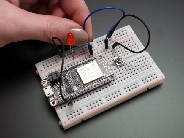
After uploading the pushbutton code to your board, you should have a circuit that lights up an LED when the button is pressed. Next we'll add in some code to send a message to Adafruit IO each time the button is pressed, and create a corresponding feed to catch that incoming data.
Attachments

Step 2: Create Adafruit IO Web Feed
Create a new feed in your Adafruit IO account, and name it "command."
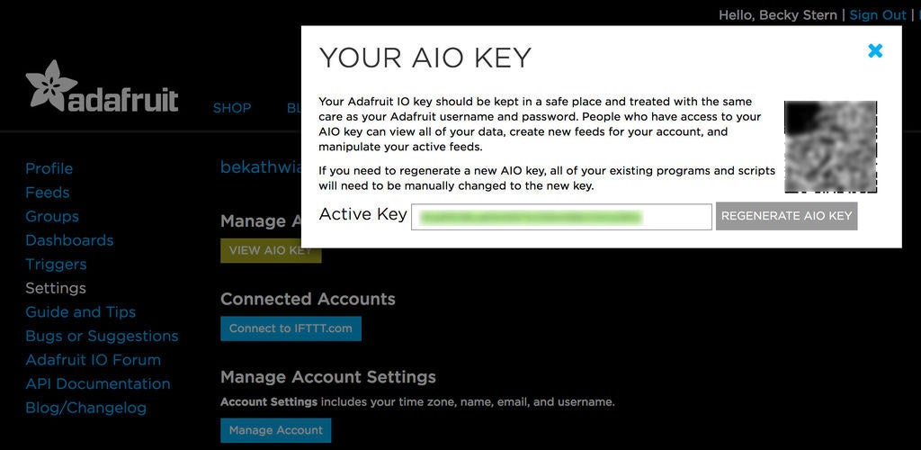
Find your AIO key on the Settings page.
Step 3: Upload Code to Connect to Feed

Download the project code attached to this step and open it with the Arduino IDE, then update the settings to match your Adafruit IO username and key as well as your wifi network name and password. Be sure you have the Arduino libraries "ArduinoHttpClient", "Adafruit IO Arduino", and "Adafruit MQTT" installed. Upload the code to your board.
Attachments
Step 4: Troubleshooting With the Serial Monitor
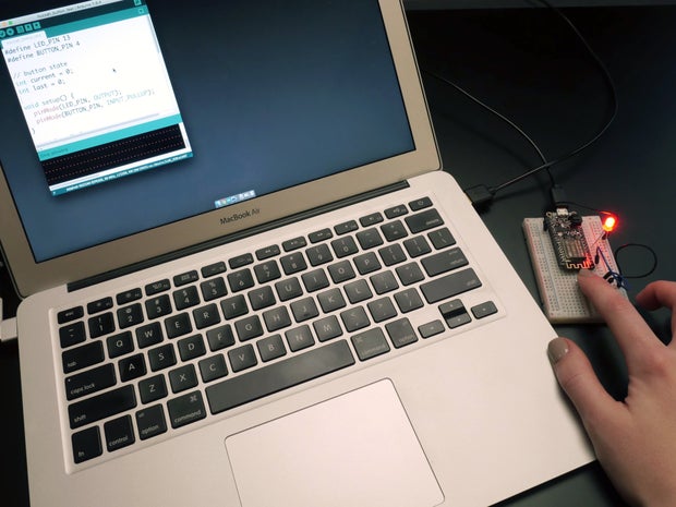
The serial monitor is an indispensable tool in your Arduino toolbox. The sample sketch is composed with helpful status updates that print to the serial monitor while the board is connected to the computer. In the Arduino software, you can open it up by clicking the magnifying glass button in the upper right of your sketch window, and set the baud rate to 115200 (matches the serial port created in the code’s setup function). Press the reset button on your board to start its sketch from the beginning, and see what info pops up in the monitor.
Does everything appear to be in order with no errors in the Arduino software? Cool, that means you've probably got data in Adafruit IO to check out! Navigate to your "command" feed in the browser and check to see what your data input looks like so far. (Once logged in to io.adafruit.com, click on "Feeds" on the left side of the page, then click on the name of your feed, "command".)
Once again, if you get an error, try to read it and troubleshoot the problem with a few things you know to look out for:
- Board connected with data-capable cable
- Correct board and port selected in tools menu
- AIO and wifi credentials typed/pasted correctly
- Internet connection is active
And a few that may be new:
- Check to see that Adafruit IO is up with no issues (check blog/forum linked on left side of page at io.adafruit.com)
- Incorrect baud rate selected in Serial Monitor
- Feed name in Arduino sketch does not match AIO feed name
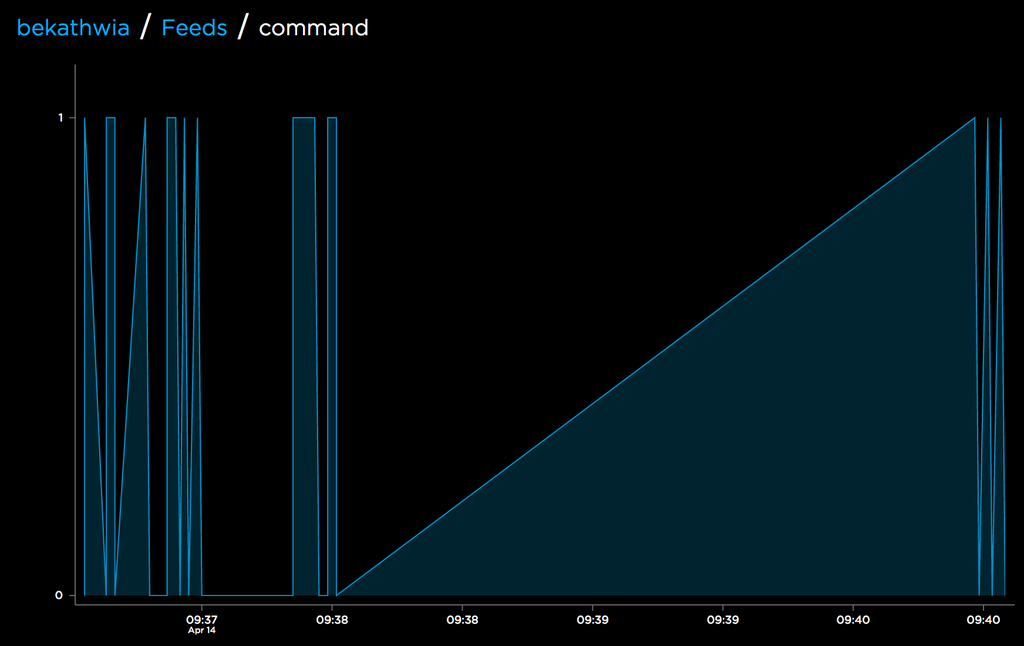
The resulting graph shows each time you pressed the button, along an axis of time. Now that we've got a working prototype that sends data to Adafruit IO, let's add an online service to watch the feed and take actions based on it.
Step 5: Connect IO Feed to IFTTT

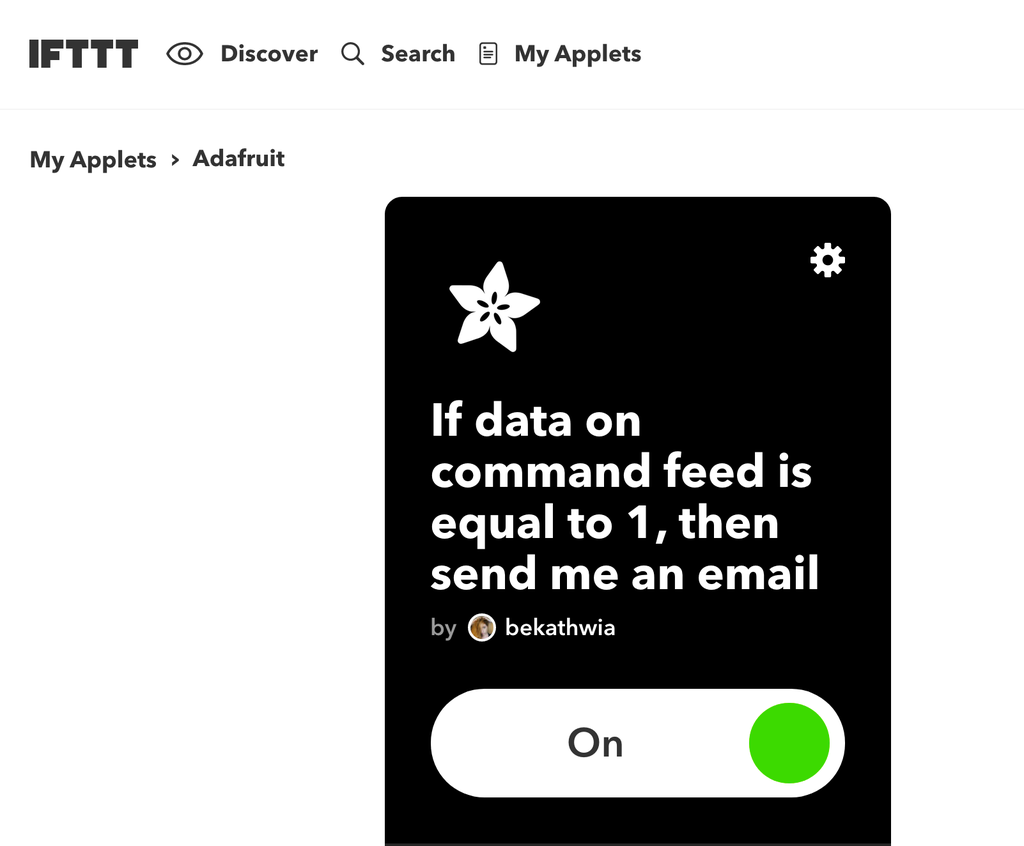
Sign in to your IFTTT account and click My Applets at the top of the page, then the button marked "New Applet" on the right of page. Click "+this" to choose an input service, and start typing "Adafruit" into the search bar until it appears, then click the button marked Adafruit to see the available triggers. For this example, either trigger will work, but for the sake of showing more settings, choose "Monitor a feed on Adafruit IO."
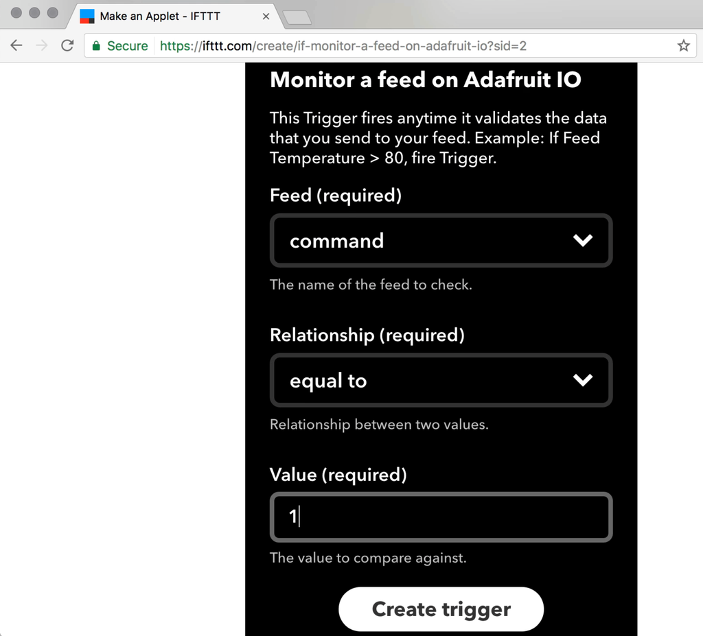
From the dropdown menus, select the feed name "command" and the relationship "equal to". Type the number 1 into the Value field, then click the button marked "Create trigger".
Next, click "+that" to choose an output service, and then click "email" (or choose a different output service like Twitter, SMS, etc.). Click through to customize the email message, then click the button marked "Create action". Lastly, customize the name of the applet (if you wish) and click the button marked "Finish".
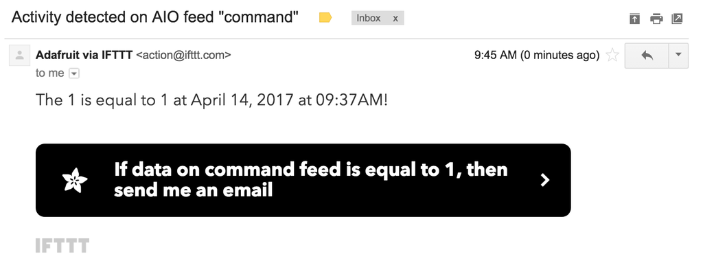
Now when you press the button, you should see an email in your inbox (up to a few minutes later).
Step 6: Switch Up Your Input

Buttons are all well and good, but they are just the tip of the input iceberg. Now that you've got a basic switch circuit working, you can swap the button out for any normally open switch without changing the code (or at most, changing line 17 to evaluate for HIGH instead of LOW). Here are some ideas:
Learn more in the Switches lesson of Randy's Electronics Class!
One particularly fun upgrade to this circuit is to add a PIR motion sensor. PIR stands for Passive Infrared, which describes how the sensor works— by detecting changes in the overall amount of IR light it can "see" with its collector dome. This sensor is designed to output a simple HIGH/LOW signal when its (adjustable) threshold is exceeded, so we can easily use it in place of a pushbutton using the same circuit we've been using all along. In addition to the PIR motion sensor, grab a one more wire (for powering the sensor), a 10K ohm resistor (brown, black, orange, gold) and wire them up according to the following circuit diagram:
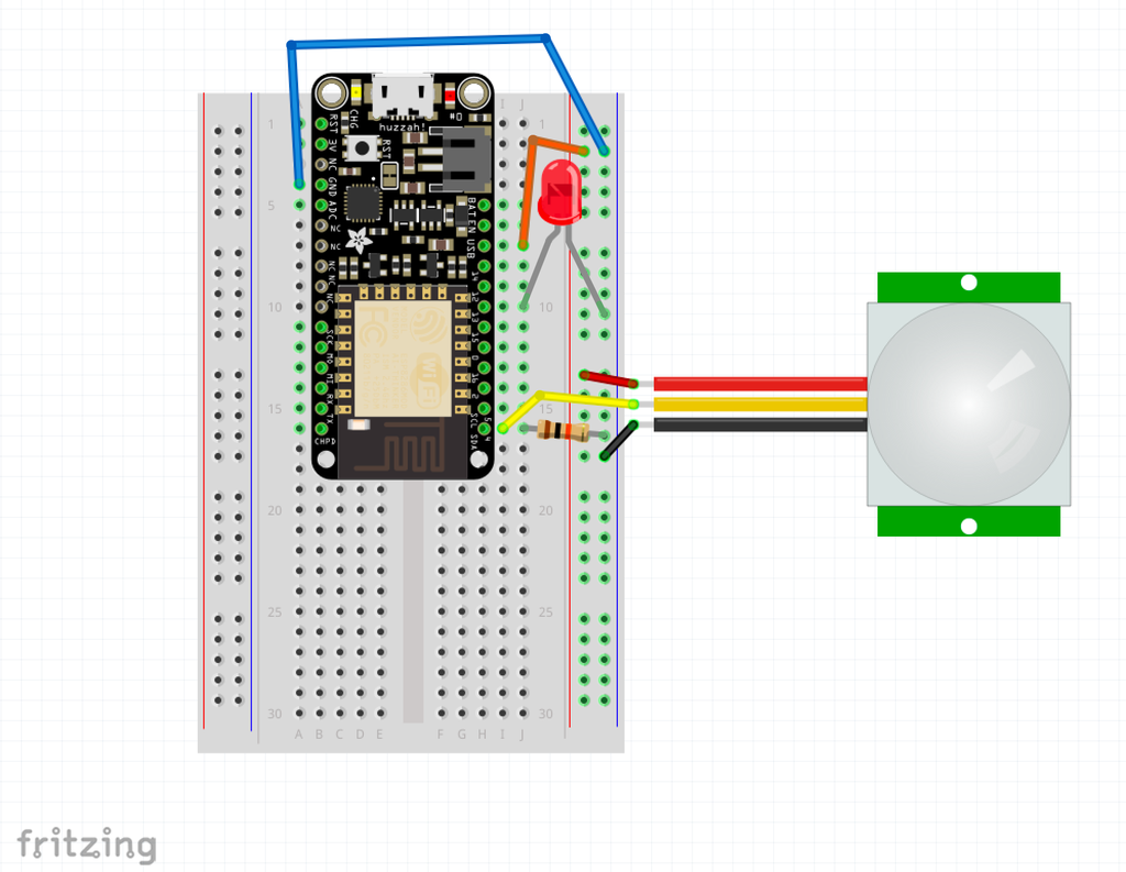
The PIR motion sensor comes with a wired three-pin connector that plugs into three header pins on the sensor board— the black wire should line up with the pin marked GND.
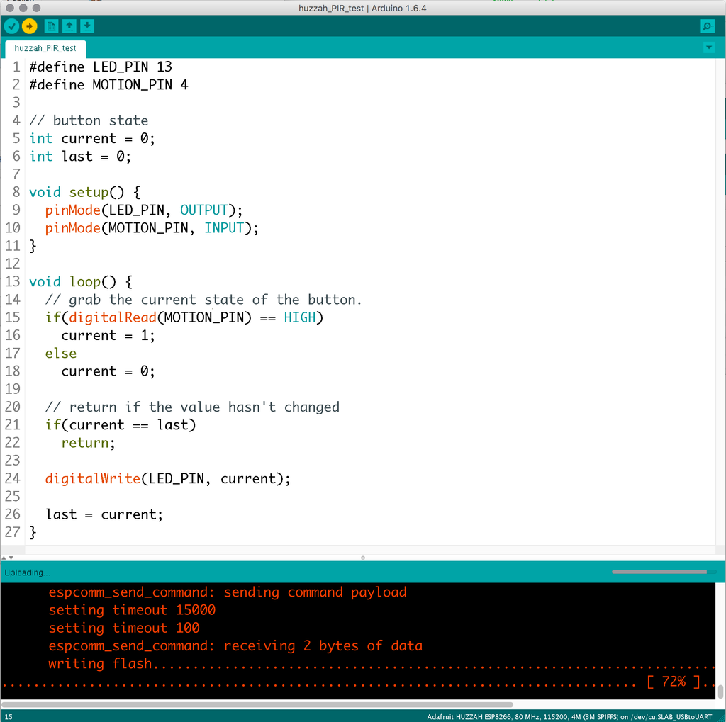
The code to test the motion sensor is very similar to the button test code, with some minor (but significant) changes. Since the motion sensor sends a HIGH signal when it detects movement, we'll need to remove the internal pull-up resistor from the pinMode declaration in the code's setup, and change the main if statement to check for a HIGH signal instead of a LOW.
#define LED_PIN 13
#define MOTION_PIN 4

// button state
int current = 0;
int last = 0;

void setup() {
  pinMode(LED_PIN, OUTPUT);
  pinMode(MOTION_PIN, INPUT);
}

void loop() {
  // grab the current state of the button.
  if(digitalRead(MOTION_PIN) == HIGH)
    current = 1;
  else
    current = 0;

  // return if the value hasn't changed
  if(current == last)
    return;

  digitalWrite(LED_PIN, current);

  last = current;
}
Copy or download this code into your Arduino software (a new blank sketch, please), or if you're feeling adventurous, make the two small changes we just mentioned to your button test code by hand and save the file with a new name, such as huzzah_PIR_test.ino.
Upload the PIR test code to your Feather Huzzah and test that waving your hand in front of the sensor causes the LED to light up for a few seconds, then turn off again. You can adjust the sensitivity of the trigger and the duration of the HIGH signal by turning the sensor board's tiny potentiometers with a small screwdriver.
Attachments
Step 7: Taking It Further
The Feather Huzzah has several pins capable of reading a digital input. Avoiding the special pins that cause the board to enter bootmode, the logical choices for adding more switches are pins 5, 16, 13, 12, and 14.
Using an analog sensor like a photocell or potentiometer with the ESP8266 is a bit trickier than just plugging it in and calling analogRead(); because the analog to digital converter (ADC) has a 1V maximum. To scale down a 3 or 5 volt sensor signal, you must build a voltage divider, which is composed of a few carefully selected resistors. There is only one ADC on the ESP8266, and it's in code it's called A0. For example, you might divide the 3V resisted by a light-dependent resistor with a 10K ohm resistor to scale its output to within the 0-1V range.
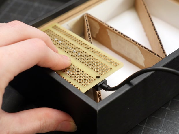
After creating a breadboard prototype, the next logical project step is to make a more permanent, soldered version of the circuit. Consider some of the following factors as you design:
- How will it be powered— USB direct/battery bank, Lipoly battery, other? Know your power requirements.
- Where will it be used— will it be exposed to friction, weather, humidity? Protect your circuit, and use an enclosure or mounting technique that is suited to the function.
- Think safety— don't leave DIY electronics projects alone with your pets or small children.
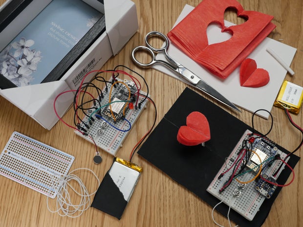
What would you make with this circuit, code, and web configuration? To complete this lesson, post up an idea or sketch for a project you'd like to make, or a photo of your trigger circuit, in the I Made It below. I'm looking forward to checking them out and also answering your questions in the comments.
Internet of Things Class table of contents:


