

Introduction: 12-Pin 7 Segment Display Wiring Tutorial


The 12-pin 7 segment display seemed quite difficult to find tutorials or a good data sheet for when I first started working with it. Thus, I decided that an instructable on how to wire it up and some basics on how to code it in MPIDE (also will work in the Arduino IDE) would be a great resource.
The LabVIEW Interaction Parts Kit includes a 12-pin 7 segment display. In the near future, once you have it wired up, you will be able to use LabVIEW MakerHub LINX with some custom firmware to control your 7 segment display easily with LabVIEW. I'll create an instructable on how to set that up once the new version of LINX comes out so stay tuned!
Step 1: Materials


1. A microcontroller (such as a chipKIT WF32)
2. A breadboard (found in the LabVIEW Interaction Parts Kit)
3. 4 digit 12-pin 7 segment display (pictured above and found in the LabVIEW Interaction Parts Kit)
4. 4x 240 ohm resistors (found in the LabVIEW Interaction Parts Kit)
5. Wires
Step 2: A Brief Overview
Seven segment displays have, like the name suggests, seven segments. These segments are usually labeled A-G and some seven segment displays even have a decimal point that you can light up. For multiple digit displays, usually only one digit is shown at once by writing a specific digital line high or low.
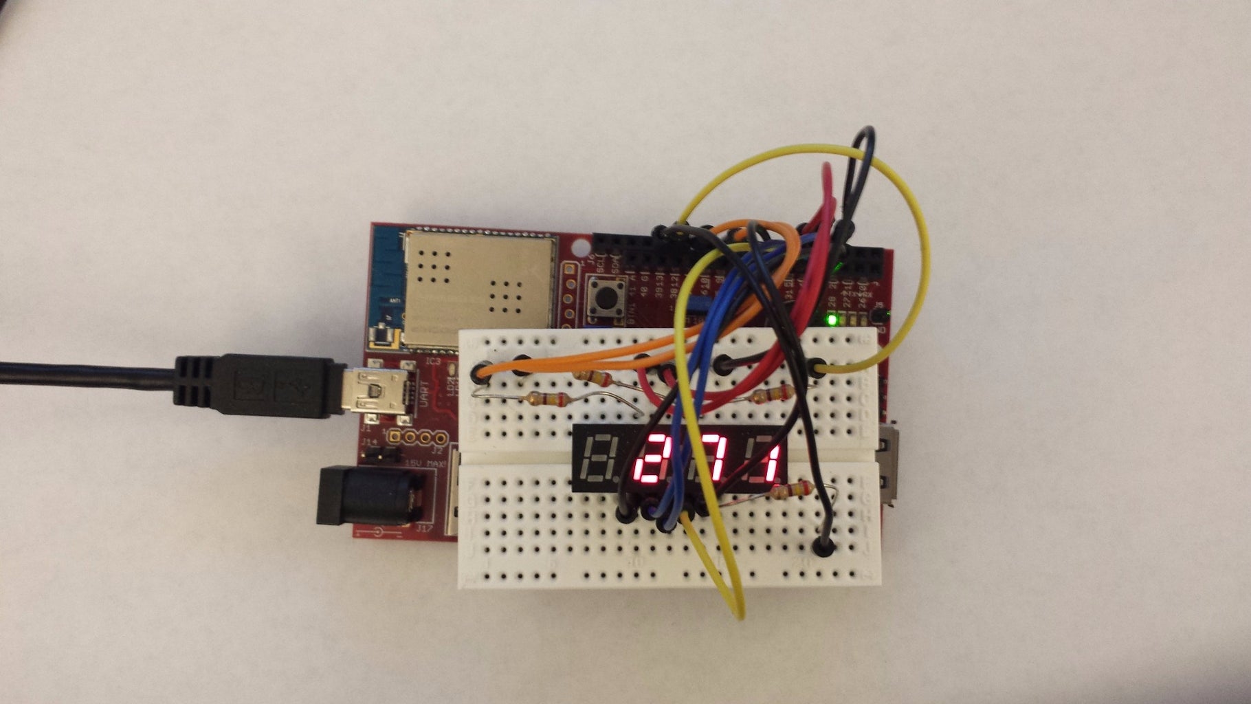
To display a number that is more than one digit (ie 271), your code must set the segments to display a "1" and then light up that digit. Then your code will "erase" the segments and then set the segments to display a "7" and then light up the digit to the left of the first one. The same is done to display the 2.
If your code switches between displaying each of the individual digits fast enough, it will appear as if all of the digits are being displayed at once! This trickery is called persistence of vision and is accomplished using multiplexing (the technique described above).
In order to wire up the seven segment display, we'll need digital lines for the 7 segments (and another for the decimal point) and then 4 more digital lines to select which digit to display. This gives a total of 12 pins!
Step 3: Wiring


Alright now that we have an understanding of how it works, let's wire it up. Refer to the picture above so you know which segment corresponds to which letter we describe it with! Also check out the picture with the labeled pins. Anodes 1-4 are used to determine which digit is on.
For each anode line, you'll need to connect a 240 ohm resistor between the pin and the digital channel you'll be connecting it to.
Connect segments A, B, C, D, E, F, G, and DP to pins 5, 3, 32, 30, 29, 4, 33, and 31 respectively. Connect Anode1 to pin 9 and Anodes2-4 to pins 11-13 respectively.
Step 4: Example Code


Writing the digital channel that the segment is connected to LOW will turn that segment on. The "anode" channels determine which digit is displayed. Only one anode channel is high at a time to display the corresponding digit. To display the first digit, you'd write Anode1 HIGH and Anodes2-4 LOW.
Here is some (admittedly poorly written) example code that I created. If you open the serial monitor at 9600 baud, you can send the value that you want the 7 segment to display. If you're using the Arduino IDE, you can just copy paste the code and it will work.
Stay tuned for a wiring tutorial for a LED matrix (without a driver) and the custom LINX firmware so you can easily control the 7 segment display with LabVIEW!
Attachments


Participated in the
Tech Contest


