

Introduction: Arduino Logic Probe


This project is an instrument of measuring so that you can measure logic levels of voltage. That is, with an Arduino Uno, and a 3-digit common cathode display, you will probe logic levels as zeros and ones, even pulses. For obtaining the code, you can go to: http://pastebin.com/cCBQLDyU
What you will need:
Soldering iron and solder
Wire strippers and cutter
Needle nose pliers
Multimeter
22 AWG wire, 1 meter
Step 1: List of Materials


1 Arduino Uno Proto Shield (PCB only)
1 ABS Plastic Enclosure for Arduino Boards - Fits UNO or MEGA
1 Displays Segmented Panel 3DIGIT 24LED Orange CC 12-Pin DIP
1 Arduino Uno R3 DIP Edition (Revision 3)
7 Resistor Carbon Film 220 Ohm 1/4 Watt 5%
1 Resistor Carbon Film 10k Ohm 1/4 Watt 5%
1 Connector Unshrouded Header 40 Position 2.54mm Straight Thru-Hole
1 Test Lead Red
1 Cable USB2.0 A/B 3 Feet Black USB-A Male To USB-B Male
1 9V Battery Snap with 2.1mm Barrel Plug
Step 2: Schematic Diagram

This is the project's general diagram where you see each connection for carrying out your project successfully. That is, it's an easy way of following the project and with it to avoid errors.
Step 3: Identifying the 3 Digit CC Display

Observing carefully this Display, you will connect correctly the device because the corresponding pins are exactly the same, the picture and the component physically.
Step 4: Installing the 3-Digit CC Display
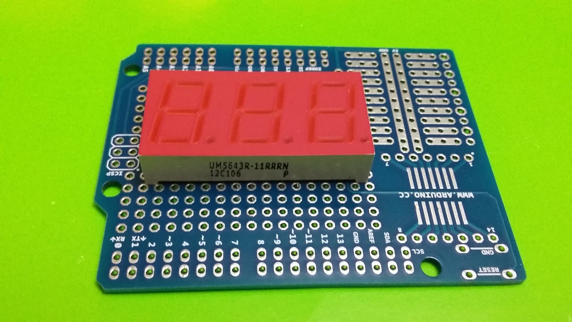
Installing the led display, you can realize how it is fitted perfectly in the PCB. This photo is to your help.
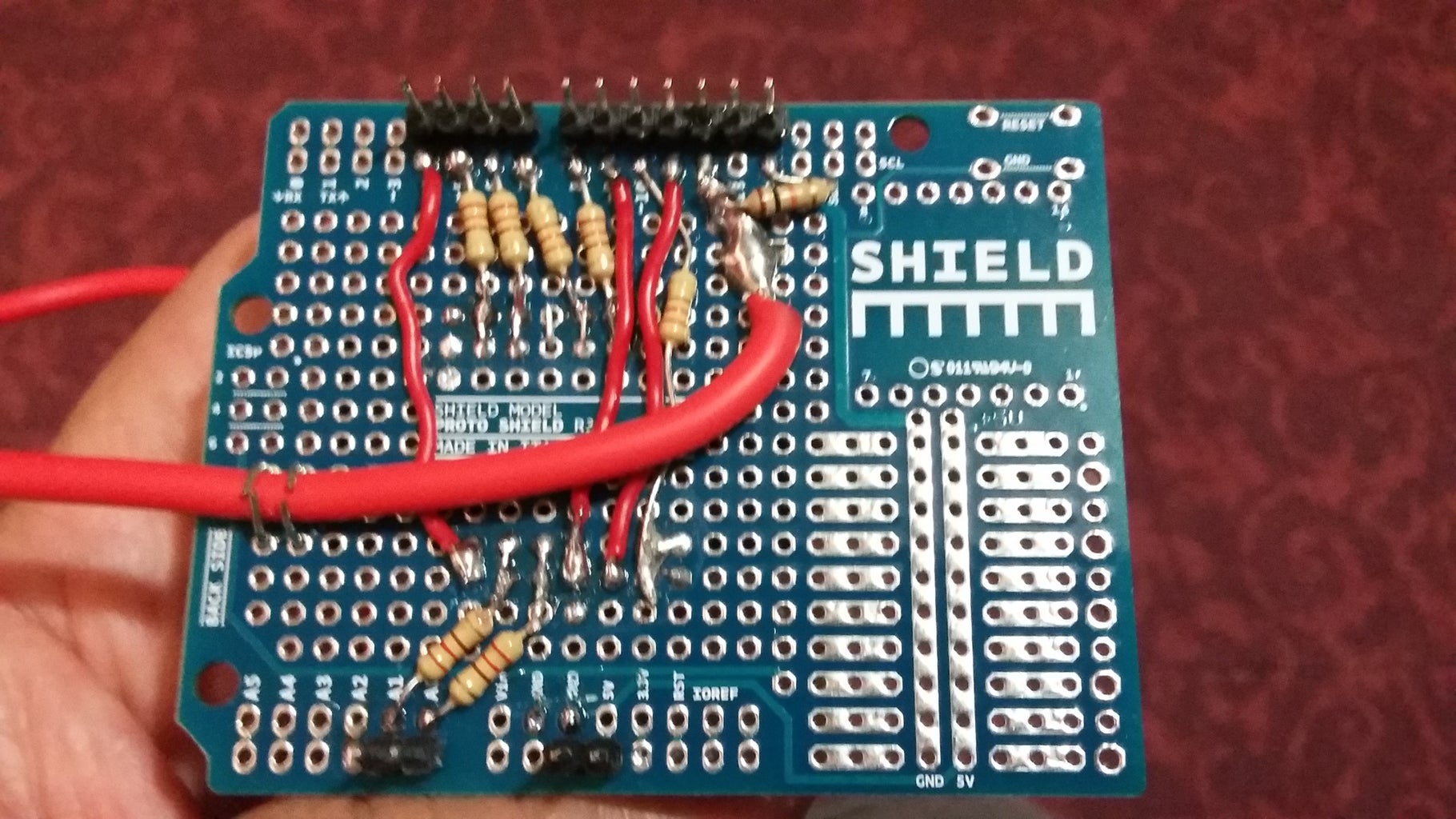
Step 5: 3 Digit Back Side CC Display

This picture describes how to make each connection to your display. In this side of the PCB, follow the instructions to avoid errors. Note the clear directions to connect correctly the 3-digit display.
Step 6: Connecting the 3-Digit CC Display to Its Resistors

With the step #5 and the help of the project's diagram, install and solder the resistors to your display and Arduino pins respectively.
Step 7: Completing the Connections to Your Display

This picture shows how to complete the rest of connections to your display. To complete this step, make the connections to the common display pins, d1, d2, and d3.
Step 8: Installing the Resistor 10K

This picture shows how to connect the resistor of 10K to Arduino pin 10 and GND respectively. Also, the connection of GND to GND close to 5V pin on your PCB.
Step 9: Preparing the Pins

Taking the Connector Unshrouded Header 40 Position 2.54mm Straight Thru-Hole, cut the pins that you will need to install in the project.
Step 10: Inserting the Pins Into the Arduino

Install the pins previously prepared in the step #9.
Step 11: Soldering the Pins

This picture shows the pins are already installed and soldered.
Step 12: Front View After Installing the Pins

With this front view of your project, you can realize if everything is OK.
Step 13: Preparing the Test Lead

This picture shows how to prepare the test lead of your project.
Step 14: Installing the Test Lead
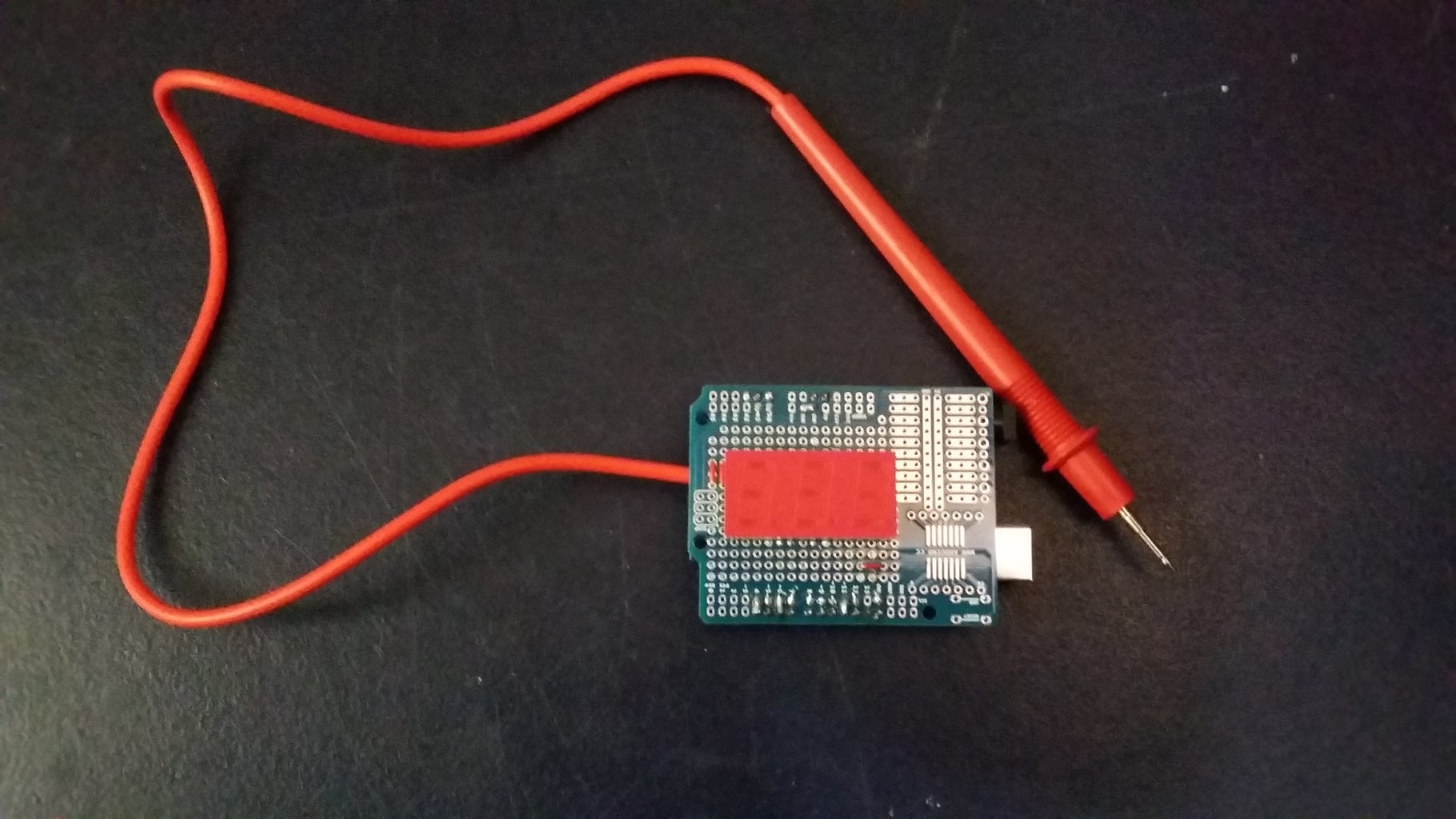
This picture shows how to install the test lead.
Step 15: Front View After Installing the Test Lead
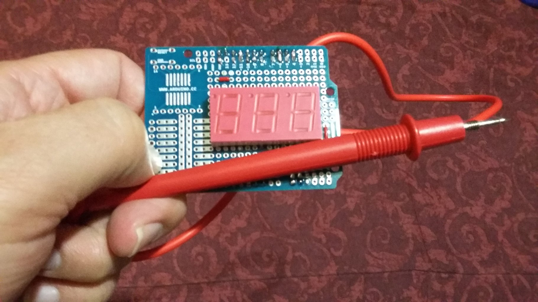
In this front view of your project, you can verify if everything is OK with help of the schematic.
Step 16: Mounting the Project on the Arduino
With this front view of your project, you can already think on an enclosure.
Step 17: Mount Your Project on the Arduino Enclosure

Mounting the project on the Arduino enclosure, you can already think about the code.
Step 18: Uploading the Code

Upload the code so that you can use it to measure logic levels of voltage. Also note before measuring something, you will only see zeros because nothing is measured; and therefore, zero voltage is detected. For uploading the code, you can go to: http://pastebin.com/cCBQLDyU
Step 19: Checking a Low Level of Voltage ("0")

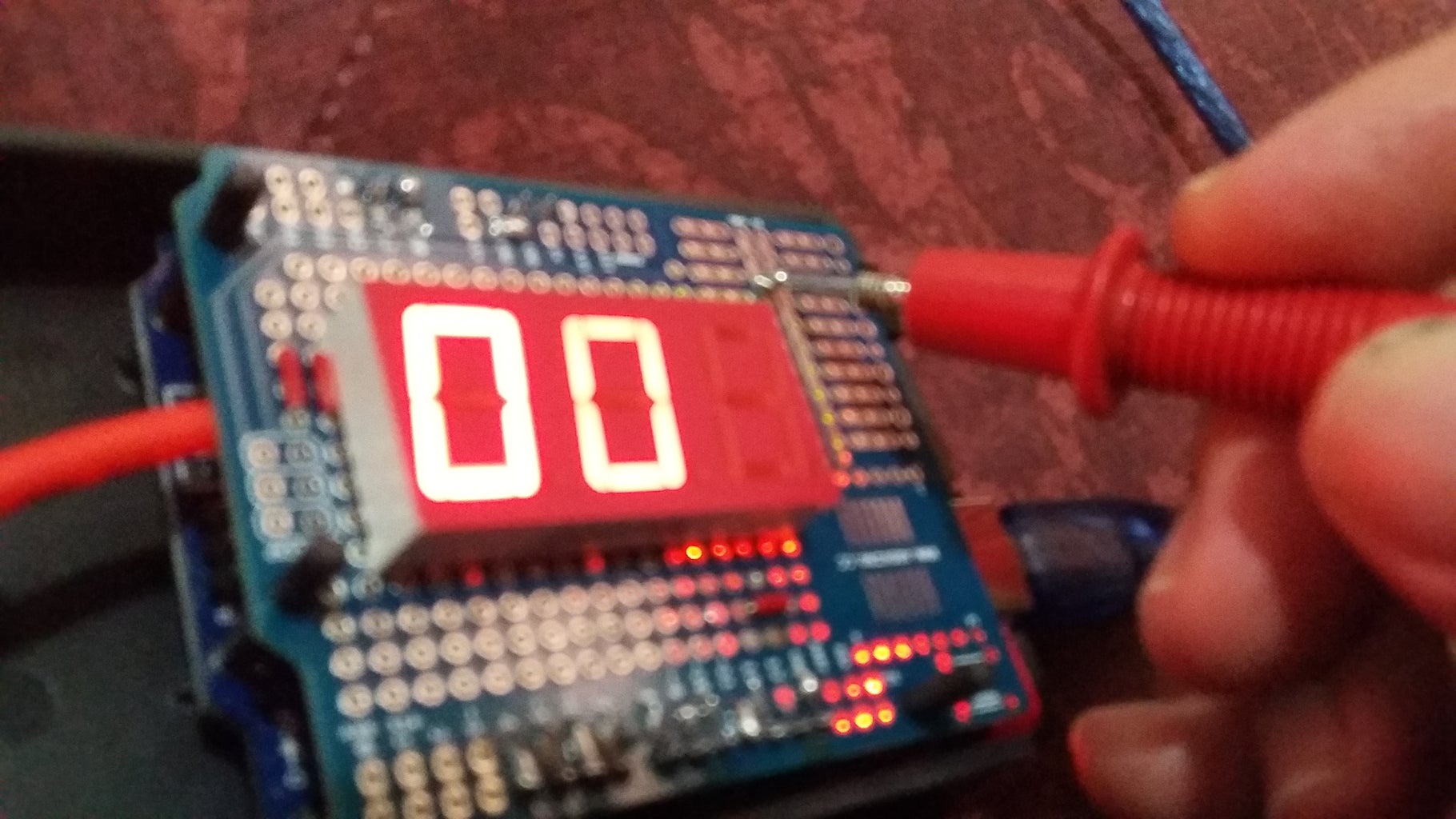

Once uploaded the code, you can already measure logic zeros.
Step 20: Checking a High Level of Voltage ("1")
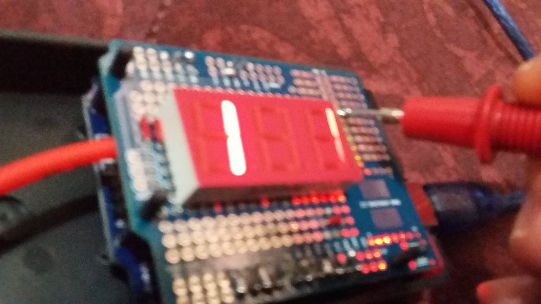

Once uploaded the code, you can already measure logic ones.


