

Introduction: Arduino Nano Logic Probe
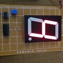


This project is a new version of my Arduino Logic Probe, but now constructed with an Arduino Nano instead of an Arduino Uno. A 3-digit display, a few resistors, and the Arduino Nano are practically the components of this interesting project that also did with EasyEda software. This tester can only test "0's" and "1's" from +5V TTL circuit.
Step 1: Bill of Materials


What you will need:
1 PCB (EasyEda Design)
1 Common Cathode 3-Digit Display (red)
1 Arduino Nano (included 2:15-Pin Straight Single Row Male Header)
6 Resistors of 470 Ohm
1 Resistor of 10K
1 Alligator Clip Test Lead with two alligators
3 Male to Male Jumper Wires
1 Soldering iron
1 Solder roll
5" Heat shrink tubing (1/4")
Step 2: Arduino Nano Logic Probe's Diagram

Carefully Follow the diagram of your project because you only need insert the components and solder them.
Step 3: Install 3-Digit Display


Once installed the common cathode 3-digit display, you should proceed to solder. Check your diagram in the previous step.
Step 4: Insert the Resistors of 470 Ohm & 10K


Note that R7 is 10K (brown,black, orange) while R1 to R6 are 470 Ohm (yellow, violet, brown). Insert their terminals and fold them so that you can later solder.
Step 5: Insert the 2:15-Pin Straight Single Row Male Header


Only insert them.
Step 6: Place the Arduino Nano


Carefully place the Arduino Nano, permitting the inserting of the pins previously inserted in the PCB. Once placed your Arduino, you can proceed to solder on so that you can later solder under PCB.
Step 7: Upload the Code


Upload the code from: https://pastebin.com/RRAa1SvQ
Step 8: Take the Alligator Clip Test Lead With Two Alligators

Fold it at middle.
Step 9: Cut the Wire

Cut the wire that you previously folded.
Step 10: Remove Plastic Insulation

Prepare the wires so that you can solder them.
Step 11: Solder the Positive Terminal

Take a male to male jumper wire for preparing the positive terminal and before joining it with the alligator wire. Note, you should install a piece of heat shrink tube on the yellow wire.
Step 12: Solder the Negative Terminal

Take a male to male jumper wire for preparing the negative terminal and before joining it with the alligator wire. Note, you should install a piece of heat shrink tube on the yellow wire.
Step 13: Slide the Heat Shrink Tube

Now, slide the heat shrink tubes.
Step 14: Complete the Process of Terminals

You can use a hair dryer to complete the process.
Step 15: Insert the Terminals Constructed


Insert the terminals previously constructed and solder them in its respective place, red (+) and black(-).
Step 16: Insert Logic Probe (LP) Terminal


Take a male to male jumper wire and insert it into the LP hole and solder it under PCB.
Step 17: Probing the Project


Check if everything is OK, taking the free end of your logic probe (LP). Probing on GND and +5V for checking 0's and 1's respectively. Enjoy it !!!!

Participated in the
Epilog Challenge 9


