

Introduction: Cheap Arduino Combat Robot Control


The resurgence of Battlebots in the States and Robot Wars in the UK reignited my love of combat robotics. So I found a local group of bot builders and dived right in.
We fight at the UK ant weight scale (150 gram weight limit) and I quickly realised the traditional way to build a bot involved RC gear: an expensive RC transmitter, a bulky or expensive receiver and ESCs (electronic speed controllers) which are magic boxes that can handle way more current than is necessary for a bot of this size.
Having used Arduino in the past I wanted to try and do things differently and set myself a goal of an Arduino system that can receive a combat legal signal and control two drive motors for around USD$5 (half the cost of a cheap ESC)
To help achieve this goal I remixed this RC car instructable, reducing the weight/cost of the receiver and generating 4 PWM signals to run a cheap h-bridge chip
This instructable will focus on the Arduino control system but I'll add additional information to help new people build their first bot
Disclaimer:
Even at a small scale combat robot building/fighting can be dangerous, undertake at your own risk
Step 1: What You Need
Materials:
For the control system:
- 1x Arduino pro mini 5v (USD$1.70)
- 1x nRF24L01 Module ($1.14)
- 1x 3.3v regulator module ($0.32)
- 1x dual h-bridge module* ($0.90)
For the rest of a basic wedge bot:
- 2x micro gear motors** (cheap version, reliable version)
- 1x 2s Lithium polymer battery
- 1x balance charger
- 1x lipo charge bag
- 1x switch
- 1x battery connector
- misc wire (I used some Arduino jumper wires I had lying around)
- small screws
- (optional) epoxy
- (optional) Aluminium (from a soft drink can)
- (optional) extra LED's
For a basic controller:
Tools:
- Screw driver
- Soldering iron
- Pliers
- 3d printer (optional, but it makes life easier)
*when looking at h-bridge modules, look for a module with all 4 signal inputs next to each other, this will make it easier to attach to the Arduino later
**check out the final step for some tips on picking motor speeds
Step 2: Print a Chassis

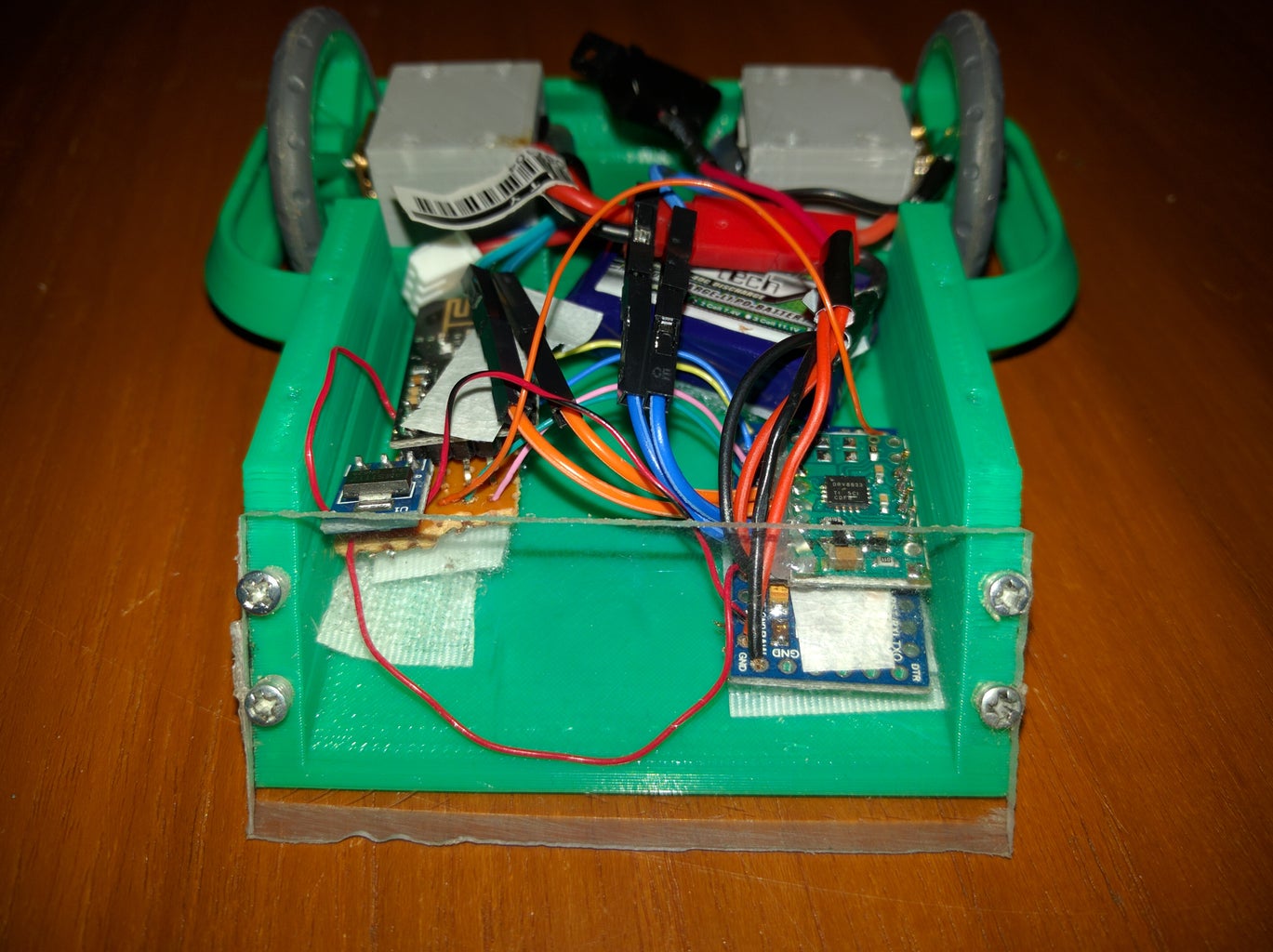
Before getting started on the control system, look at the design of the bot to be built. It's always best to design a bot from the weapon out. For a beginner, I suggest starting with a basic wedge, they are designed to be robust and push opponents out of the way meaning you are less likely to be destroyed in your first fight, plus it's easier to get a feel for driving when you don't have to worry about an active weapon.
I've designed a wedge bot: "Slightly Crude" which has been battle tested both armoured and unarmoured. It's a good first bot, easy to print and can be put together with 8 screws. Check it out on Thingiverse for a different top design
If you don't own a 3d printer, try a local library, hackerspace or maker space
Adding additional armour is easy to do fresh off the printer, sand both the wedge and the soft drink can aluminium with a course sandpaper, brush off any sanding dust, apply epoxy to both the plastic and the aluminium, hold together with clamps or rubber bands for 12-24 hours
I don't currently have a public wheel design as I have been using rubber tires from an educational robotics kit over 3d printed hubs. In the coming weeks, I'll be designing a hub that will use O-rings for grip. Once the wheels are done I'll update this page and the Thingiverse page


Step 3: Prep the H-bridge
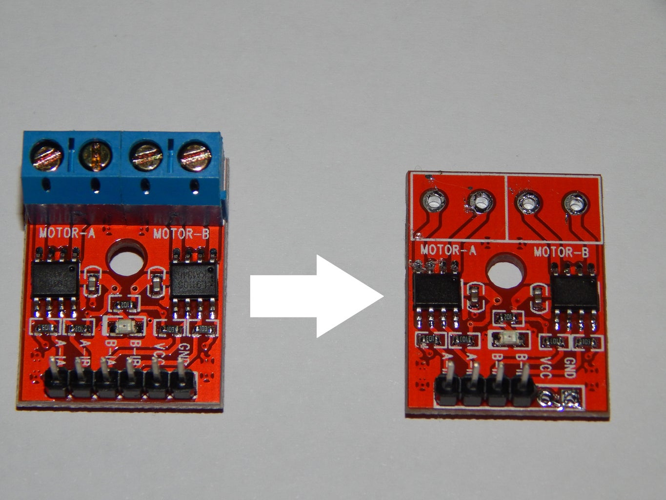
Different h-bridge motor drivers come in different set ups but the module linked in the initial list comes with 2 terminal blocks as the output. These terminal blocks are heavy and bulky so it is best to remove them.
The easiest way to do this is to heat both pads at the same time with a soldering iron and carefully wiggle the blocks out with a pair of pliers
Before moving on, decide if you want to be able to swap out the motors in your setup. If so, Arduino jumper cables can be soldered into the output of the module, then the opposite cable can be soldered to the motor, making them removable as needed.
Step 4: Wiring the Modules


Wiring the modules can be done in 3 different ways, which is why the design step is critical. Weapon choice will affect the shape of the bot and the choice of wiring.
the 3 choices are:
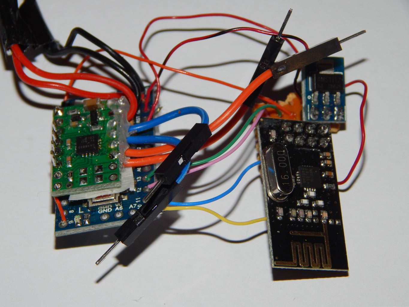
- Loose wires (light weight but more fragile) (image 1)
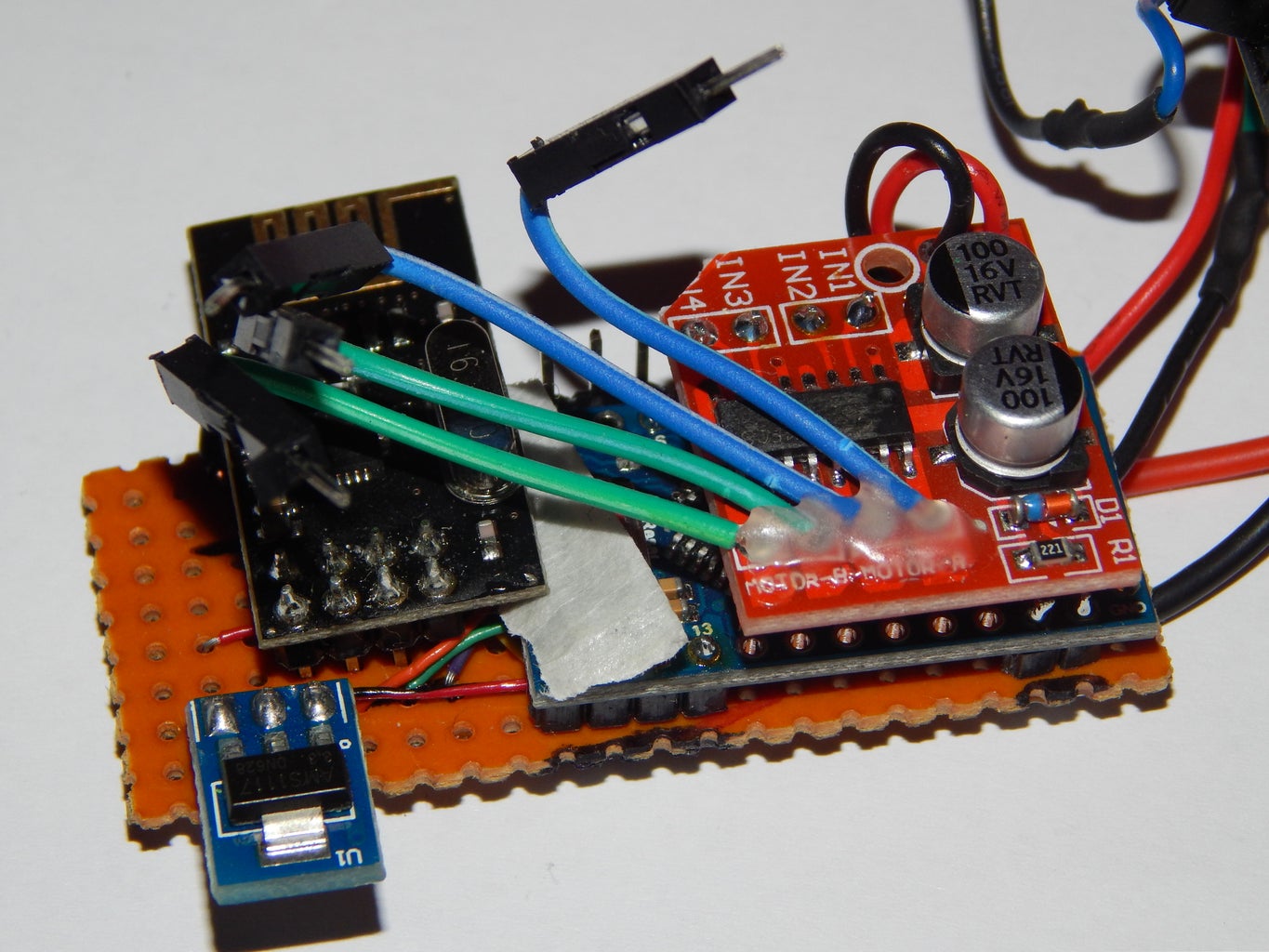
- Perfboard (heavier than 1 but more robust with a larger footprint) (image 2)
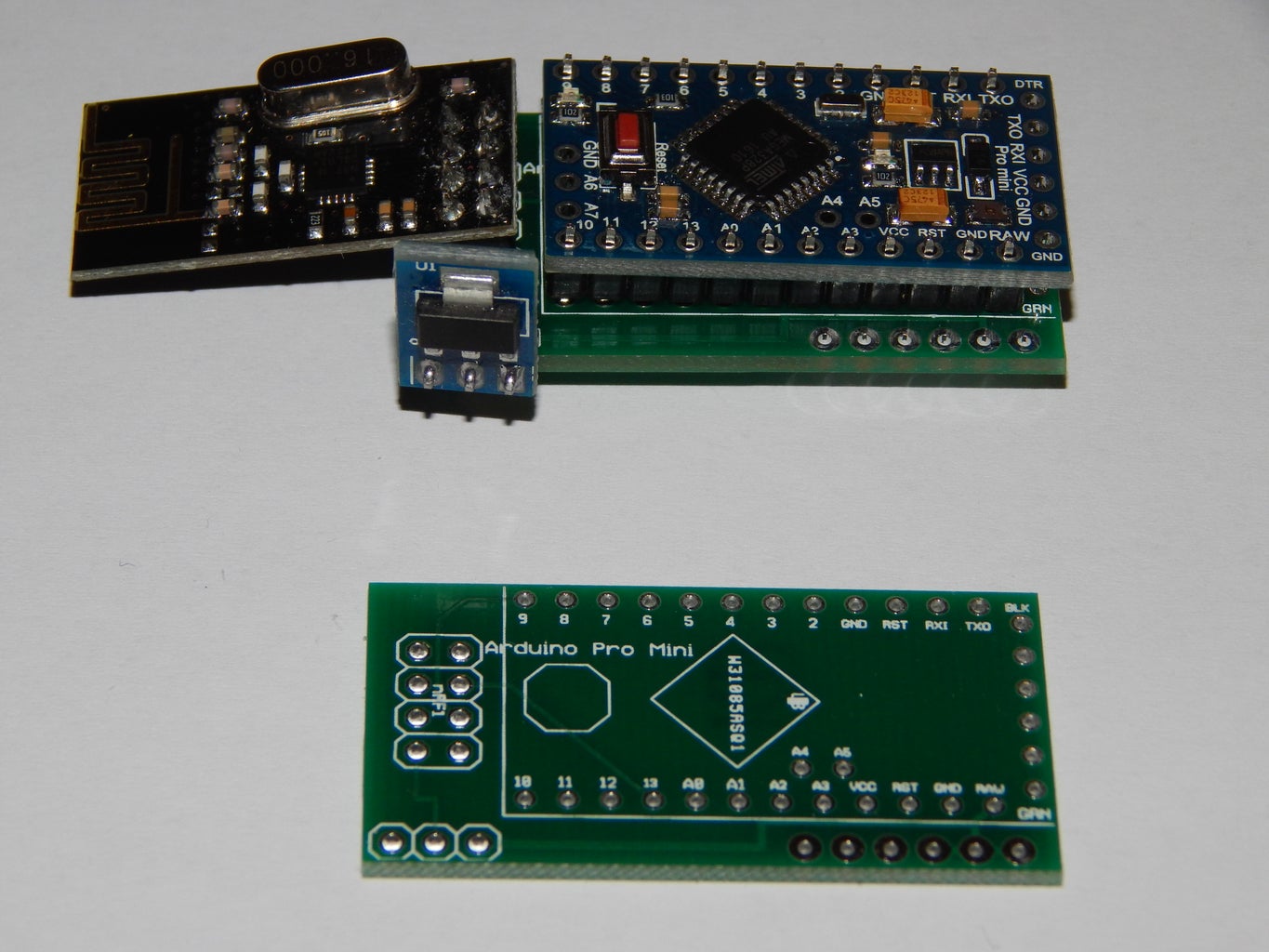
- Custom circuit board (heavier than 1 but robust with a small footprint) board design attached (image 3)
regardless of the choice made, the actual connections are the same.
Do the following connections twice (once for the controller and once for the receiver)
nRF24L01 (pin numbering image 4**):
- Pin 1 -> GND
- Pin 2 -> out pin of 3.3v module
- Pin 3 -> Arduino pin 9
- Pin 4 -> Arduino pin 10
- Pin 5 -> Arduino pin 13
- Pin 6 -> Arduino pin 11
- Pin 7 -> Arduino pin 12
3.3v module:
- Vin pin -> Vcc*
- Out pin -> pin 2 nRF (as above)
- GND pin -> GND
Arduino:
- Pins 9-13 -> connect to nRF as above
- Raw -> Vcc*
- GND -> GND
Do the following connections once to differentiate between controller and receiver
For the Controller:
Joystick:
- +5v -> Arduino 5v
- vrx -> Arduino pin A2
- vry -> Arduino pin A3
- GND -> GND
For the receiver:
h-bridge module:
- Vcc ->Vcc*
- B-IB -> Arduino pin 2
- B-IA -> Arduino pin 3
- A-IB -> Arduino pin 4
- A-IA -> Arduino pin 5
- GND -> GND
This is easiest done by replacing the pins for Vcc and GND with wire, then flipping the board upside down and soldering the pins directly into the Arduino, this simplifies the soldering and creates a sure mount for the motor driver
*for a combat robot to be legal, an isolation point (switch or removable link) must be added between the battery and the circuit. This means that the positive of battery must be connected to a switch, then the switch connected to Vcc
** image from https://arduino-info.wikispaces.com/Nrf24L01-2.4GHz-HowTo which is a great resource for the nRF24L01 module
Attachments

Step 5: Setting Up the Controller

Once everything is connected its time for some code.
Starting with the controller, some potentiometer values are needed to ensure that the exact joystick connected will work with the transmitting code.
Load in the "joystickTestVals2" code. This code is used to read the potentiometer values and display them through serial
With the code running and a serial window open start by looking at the "UP" value, push the joystick into the fully forward position, the "UP" value will likely jump between a few big numbers, pick the smallest of the values you see, subtract 10 from it (this will ensure that pushing the stick all the way will give full power) and write it down as "Up Max" allow the joystick to spring back into the center. Now pick the largest value you see, add 20 to it and write it down as "UpRestMax". Repeat the process by pushing the stick down and reversing the adding/subtracting recording the values as "UpMin" and "UpRestMin"
Repeat the entire process again for left and right, starting by pushing the stick right, recording "SideMax" then "SideRestMax" as it springs back and pushing left to record "SideMin" and "SideRestMin"
These values are super important, especially all the values containing the word "Rest". these values create the "dead zone" in the centre of the stick such that the bot won't move when the stick is resting in the center, make sure that when the stick is centred the values fall between "restMin" and "restMax" for both axes
Attachments
Step 6: Code


The code given does everything for a basic wedge-bot with a structure in place to allow for a weapon pwm value to be sent as well.
Needed Libraries:
nRF24L01 Library from here: GitHub
Software PWM from here: Google Code
Set up your controller:
open the txMix code and change the stick limit values to the values you wrote down in the last step. This will ensure that the code reacts correctly to your joystick (Image 1)
Customize pipe:
To ensure you are not interfering with anyone else at your event, you will need to change the radio pipe. This is in effect an identifier, and the receiver will only act on signals from the correct pipe, so be sure to change the pipe in both codes to the same thing.
In image 2 hex digits of the pipe have been highlighted. These are the two digits that need to be changed to customize the pipe. Change "E1" to any other 2 digit hex value and write it down so you can easily check it against opponents pipes at an event
Upload:
- txMix to the controller
- receive to the receiver module
Run down of the code:
txMix:
The code reads in the joystick position as an "UP" value and a "side" value. these values get constrained based on the max value provided to ensure full power will be given at the maximum stick postion.
These values are then checked to ensure that the stick has moved out of the neutral position, if it has not zeros are sent.
The values are then individually mixed into two variables, one for the left motor speed and one for the right motor speed. In these variables a negative value is used to indicate the motor is driving backwards as it simplifies the mixing.
The left and right speed values are then separated into four values pwm values, one for each: motor right forwards, motor left forwards, motor right backwards, motor left backwards.
The four pwm values are then sent to the receiver.
receive:
Simply receives signals from the controller, checks that the signal does not contain pwm values for forwards and backwards on a single motor then applies the pwm.
The receiver also fail safes to motors off when a signal is not received from the controller
Step 7: Bolting It All Togheter


Solder connectors to the motors or solder the motors directly to the h-bridge. (I prefer connectors so that I can simply change the plugs if I have connected the motors up incorrectly)
Solder the positive lead from the battery connector to the middle pin of the switch and one of the outer pins on the switch to the Vcc of the connected modules.
Solder the negative lead from the battery connector to the GND of the connected modules.
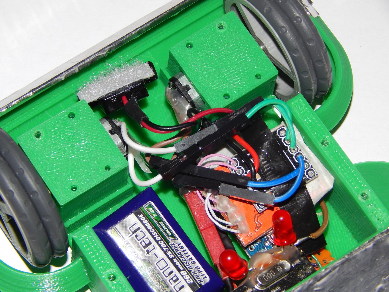
(Optional) add additional LED's between Vcc and GND. All combat robots require a light that is on while the system has power, depending on the components this system has LED's on the Arduino, the 3.3v module and the h-bridge so as long as at least one of these is visible from outside the bot this rule is met. Additional LED's can be used to be sure this rule is met and to customise the appearance
Slightly Crude is simple to bolt together, bolt the motor mounts in place first, add the electronics, then bolt the lid in place, a small amount of velcro will help hold the switch to the lid
The controller is yours to design and print. For testing, I have been using the attached controller which has been modified from James Bruton's BB8 V3 controller


Step 8: A Word on Robot Combat Rules
Different countries, states and groups run robot combat events with different rules.
I have created this system and written this 'ible to be as general as possible while hitting the major rules that pertain to RC systems (most notably the system should be 2.4GHz digital and have a battery isolation point). To run this system and or design your own first bot it is best to get into contact with your local group and get a copy of their rules.
The rules your local group runs are absolute, do not take my word in this instructable over the rules of your group.
As this Arduino system is new to the community you will most likely be asked to have it tested before using it at an event. I have battle tested this system repeatedly against standard RC equipment and against itself without any interference issues so it should pass any test, however, the organisers at your local event have the final say, respect their decision. If they reject its use, ask if there is a loan bot you can fight with, or ask for a clarification on why it was rejected and attempt to fix the issue for the next event
Step 9: Additional Information on Motors
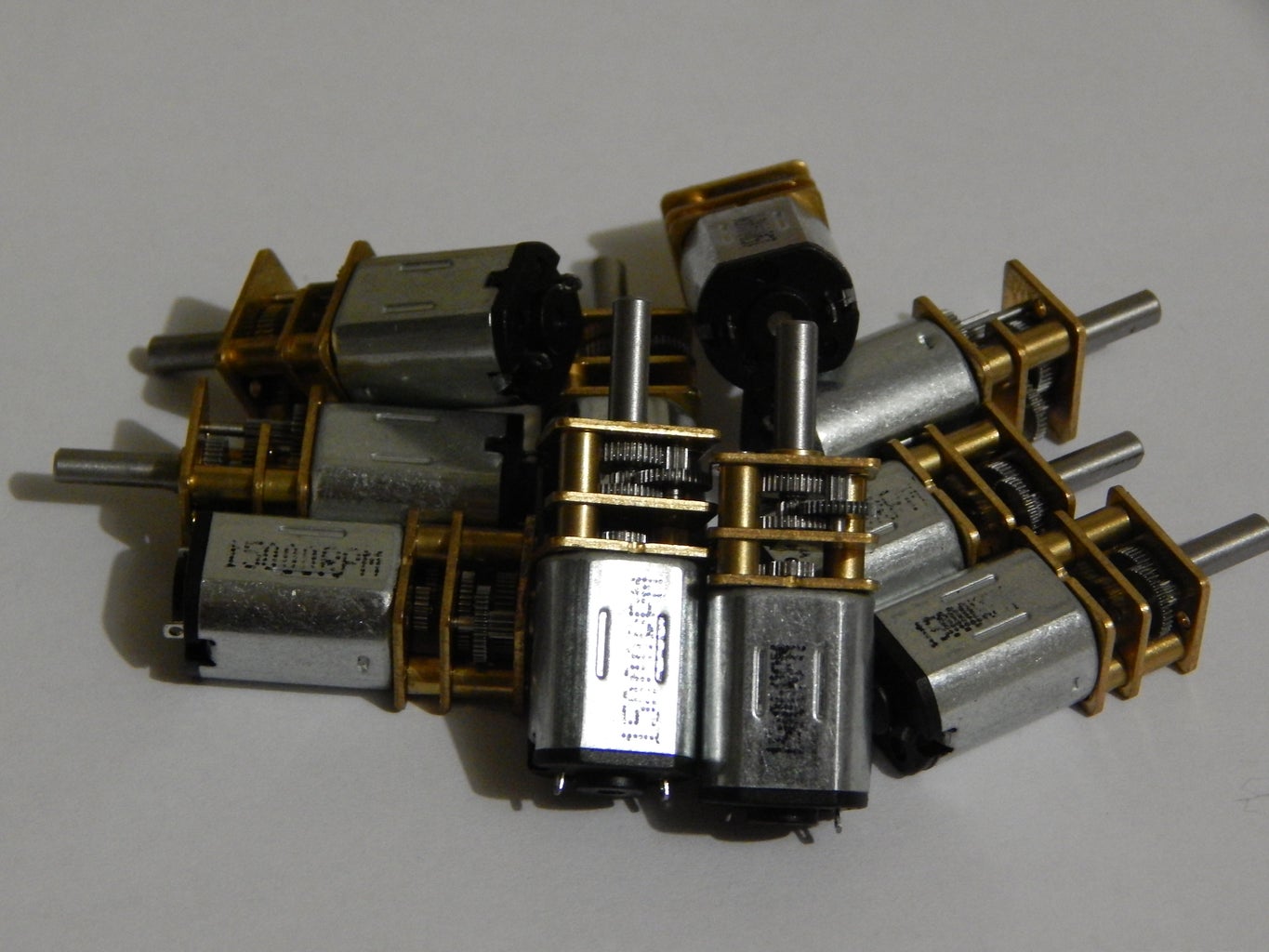
The micro gear motors used in the ant class come in a large array of speeds and are either marked using RPM or Gear ratio. Below is a rough conversion.
Most bots use motors between 75:1 and 30:1 (with some exceptions using 10:1). Bots with big spinning weapons can benefit from slower 75:1 motors as the slower speed allows more control. Nimble wedges, lifters and flippers are best on 30:1 in the hands of a skilled driver. I recommend 50:1 motors in a wedge for the first few fights just to get used to the system and driving
- 12V 2000 RPM (or 6V 1000RPM) -> 30:1
- 6V 300RPM -> 50:1
Step 10: Updates and Improvements
Its been a couple of years since I posted this 'ible and I have learnt a lot about this system so its time to update them here.
Most important is the component choice, the original components worked relatively well but would sometimes fail during combat. The 2 big perpetrators are the H-Bridge and the nrf24l01 module, due to me picking the absolute cheapest parts I could find. These can be fixed by:
- Upgrading the 0.5A H-bridge to a 1.5A H-bridge, like this one: 1.5A H-bridge
- Upgrading the nrf24l01 module to a fully SMD design: Open smart NRF24l01
Along with the new component upgrades I have designed some new PCBs that help compact the RX and add more features to the TX
I also have some code changes coming, so stay tuned for those

Participated in the
Design Now: 3D Design Contest 2016

Participated in the
Arduino Contest 2016

Participated in the
Remix Contest 2016


