

Introduction: Homebuilt (DIY) CNC Router - Arduino Based (GRBL)


Already for a few months or even years, I was planning to build my own CNC milling machine. Now I decided it was time to do it! I read a lot about other DIY projects and in the end I liked the design from the Arduino CNC intstructable that I found here. Although the dimensions were unclear and the programming and calibration was all in Spanish, I figured all that out by myself. In the end, I only used the design for reference.
In this instructable, I'll try to explain my steps, from the very beginning of the design, until the very end of your first gcode.
Note: I used a 3D printer to make some of the parts, but if you're working accurately, it's possible to make these parts from wood as well!
READ PLEASE:
I noticed some movement in my design after the first routings. A solution might be using thicker rods than the 12mm that I used. However: This design DOES work!! I'm currently still improving the design and might update this instructable in the near future! If you have any questions, please ask and I'll try to answer them.
If you like this instructable, please vote for me in the Arduino Contest. :)
Update - December 29th:I'm really blown away by all the interest you're all showing for this project! I'll try to add some results and video's this weekend. Currently I'm routing hard foam, since it's easy to test with. For harder material speeds need to be lower, otherwise the hang-though is a bit too much. I'm looking at a way to fix this (probably thicker rails) and will update this instructable as soon as possible. I know that there are some proven ways to solve this, but it's my goal to make it as cheap as possible. :)
Update - January 3rd: I added some results and video's in step 11. I'm still figuring out the CAM functionality of Fusion 360 and didn't have much time the past days, so the final 'C' is falling of the limits of the foam. ;) However: It's clear that the machine works and that some pretty good quality can be reached!
Update - January 30th: In the past weeks, I updated this instructable for the use of 18mm steel tubes instead of 12mm rods. Also, I designed more 3D printed parts for better/easier alignment of the parts. However, because of vacation and other projects, I haven't had much time to do more tests, so these will follow soon. The design is already much stiffer than before, so I guess I can increase the feedrate, even on wood.
Update - February 3rd: Waahjoo! Although I didn't update this page so much (I AM working on the machine), I just got the news that I won the First Prize in the Arduino all the things Contest! Thanks a lot to everybody who voted! I'm very happy with this!!
Have fun building!
Step 1: Materials

To make this CNC router, I used the following parts:
- 1 piece of hardwood plywood, thick 18mm, 2.44mx0.61m (€32) (local hardware store)
2 steel rods, diameter 12mm2 steel tubes, diameter 18x1.5mm, length 900mm (€5.50) (local hardware store)2 steel rods, diameter 12mm2 steel tubes, diameter 18x1.5mm, length 528mm (€3.75) (local hardware store)- 2 steel rods, diameter 12mm, length 188mm (€1.35) (local hardware store)
12x4x nylon linear bearing 12mm (€1.50) (local hardware store)- 8x nylon linear bearing 18mm (€3.50) (local hardware store)
- 2x threaded rod, M8, length 1m (€4.70) (local hardware store)
- 1x threaded rod, M5, length 1m (€2.25) (local hardware store)
- 2x coupler nut 5mm-M8 (€2) (local 3D print shop, 123-3d.nl)
- 1x coupler nut 5mm-M5 (€1) (local 3D print shop, 123-3d.nl)
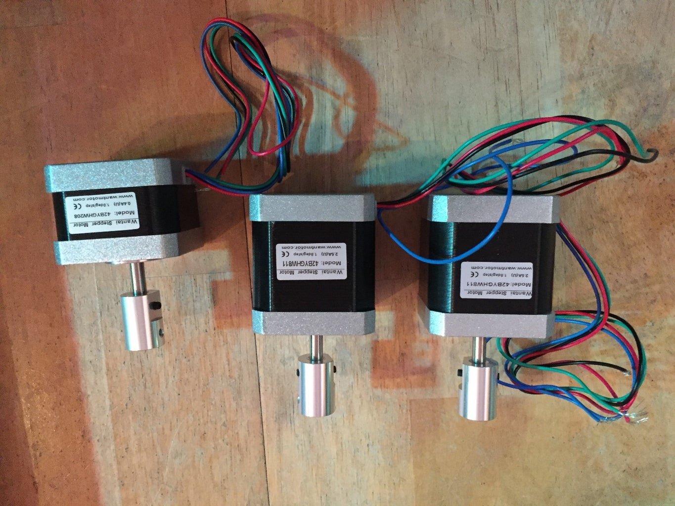
- 2x NEMA17 (Wantai 42BYGHW811) 1.8 degree/step stepper motor (€30) (local 3D print shop, 123-3d.nl)
- 1x NEMA17 (Wantai 42BYGHW208) 1.8 degree/step stepper motor (€12) (local 3D print shop, 123-3d.nl)
- 3x TB6560 stepper driver (€16.50) Ebay
- 1x 120W (12v, 10A) power supply (€10) Ebay
- 3x 4pin wire of 1 meter (€6) (local 3D print shop, 123-3d.nl)
- Some 608 ball bearings (€4) AliExpress
- 1x Chinese Arduino UNO (€2.50) AliExpress
- 1x Old laptop / raspberry pi / your own laptop (€??)
- Some M8 nuts, some M5 nuts and some screws
Total: Around €140,-
Note that this does not yet include the milling device. I used a Dremel 8200 series to start, but will change to add my normal router to it, or make something like a DC spindle onto it.
Step 2: The Design

As explained in the introduction, my hardware design is based on the Arduino CNC instructable, that I found here. Since no exact dimensions etc. were given in this instructable, I made the design all by myself again in Autodesk's Fusion 360.
I designed it to have a range of ±70cm in y-direction, ±40cm in x-direction and ±10cm in z-direction.
Step 3: The Y-assembly
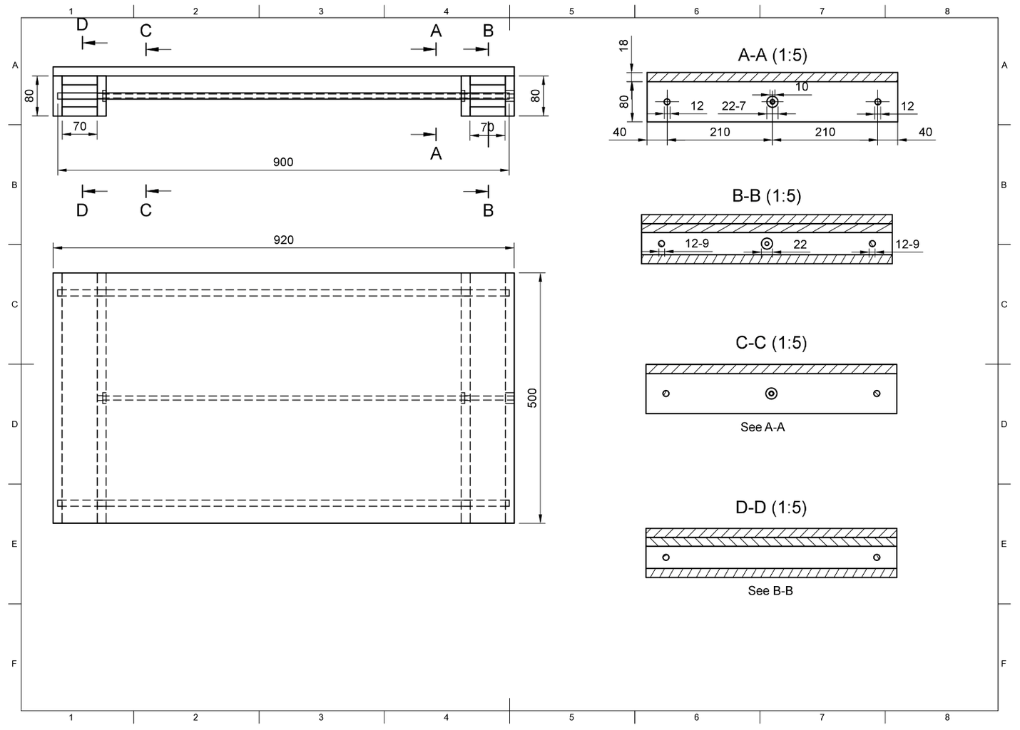


The y-assembly is one of the easiest (and biggest) parts to make. I attached a building drawing, in which all dimensions are in mm's.
Notes:
- Where 22-7 is written, this means that you need to drill a hole with a diameter of 22mm, and only 7mm's deep. This is for the bearings.
- Panel A-A and C-C are identical.
- Panel B-B and D-D are almost identical: In panel B-B you need to drill 1 22mm hole for the coupler nut between the stepper motor and the threaded rod. In panel D-D you don't drill this hole.
- The 12mm holes in panels B-B and D-D are only 9 mm deep.
Update: 12mm rods seemed to hang through too much. Therefore, the design was changed for the use of 18mm tubes. The drawing with dimensions stays the same, ONLY in case of drilling 12mm holes, 18mm holes have to be drilled!
Before screwing the 80mm and 70mm pieces together, attach the first NEMA17 42BYGHW811 stepper motor to panel B-B. Then, attach the coupling nut and the threaded rod (cut it to 750mm) to the stepper motor. Now you can screw the 70mm and 80mm pieces together but don't attach the large board yet. Otherwise we won't be able to attach the x-assembly. You'll end up with something that looks like figure 3.
Step 4: The X-assembly

The x-assembly contains some 3d printed parts. You can find these all on Thingiverse. For the x-assembly, you'll need:
- 4x XY-joint
- 2x Y-nut-holder
You can also make these parts from wood, but then you'll have to be a bit more creative yourself. :)
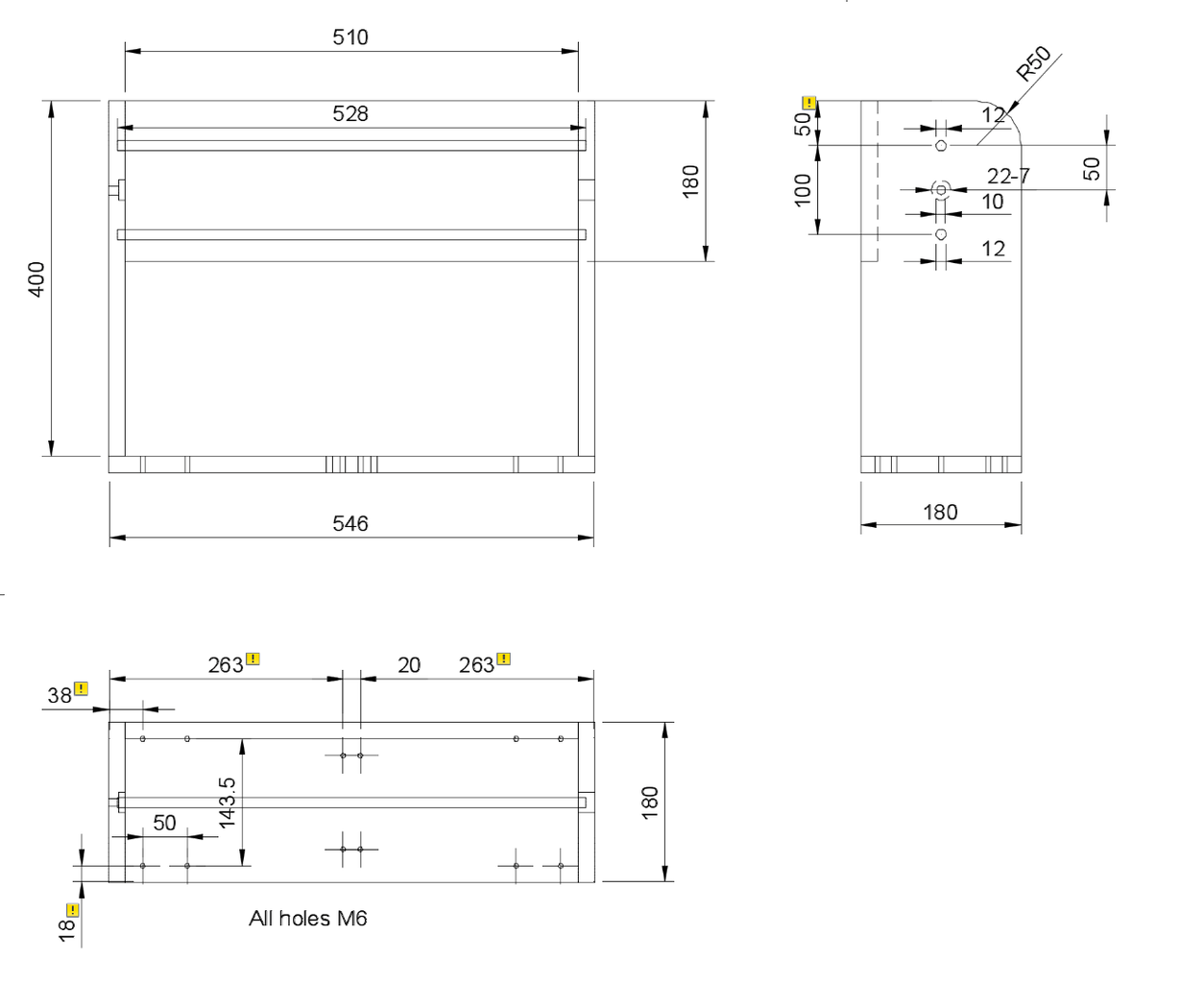
Saw the wood as shown in drawing, but don't screw all parts together before the Z-Block is finished (next step).
Note: In the left side panel, the 22mm hole is only 7mm deep (bearing) and the 10mm hole goes through. In the right panel, the 22mm hole goes through (because of the coupler nut).
Update: Just like the Y-Assembly, the 12mm rods have been replaced by 18mm tubes. Also, there are now some 3d printed parts used to help aligning these tubes. They are upload to thingiverse as well. Again: If you work accurate enough, it might not be necessary to use these 3d printed parts and make it from wood.
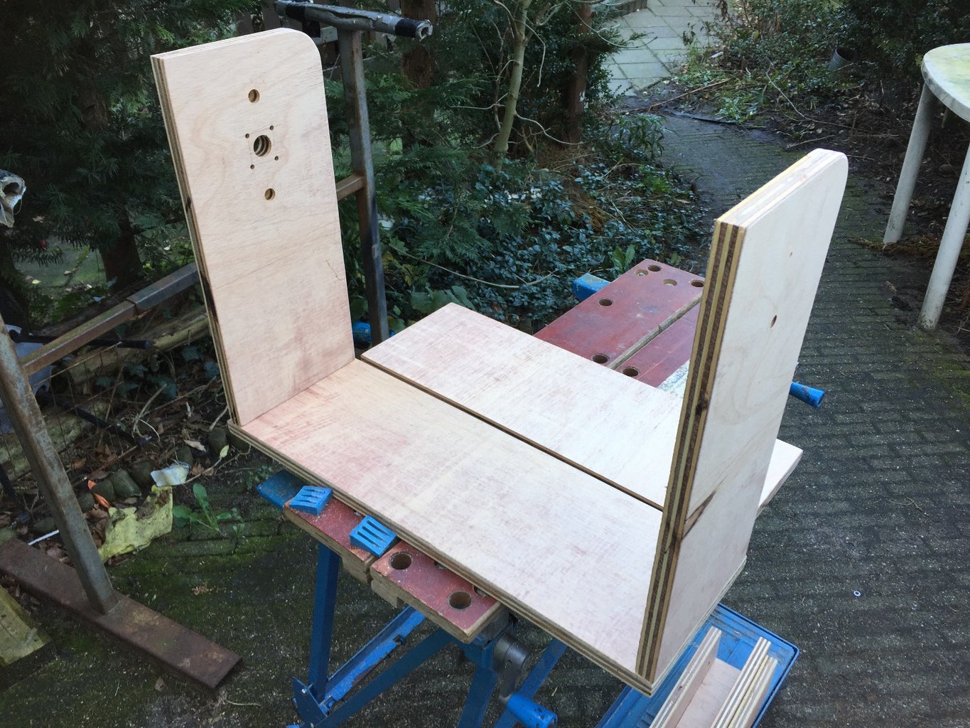
Step 5: Z-block Assembly


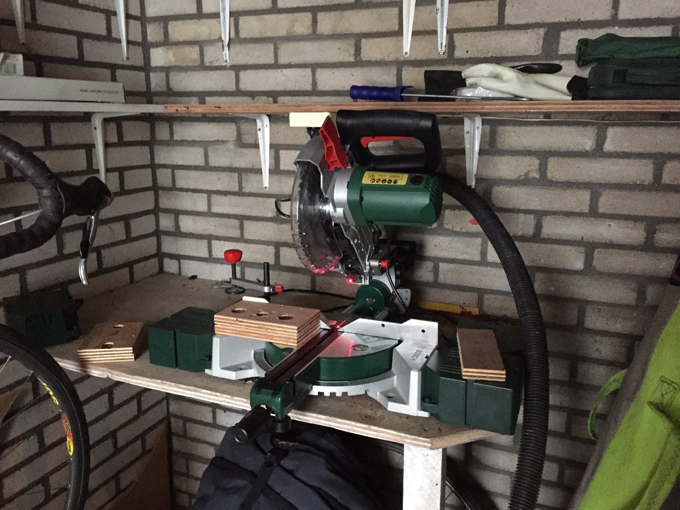
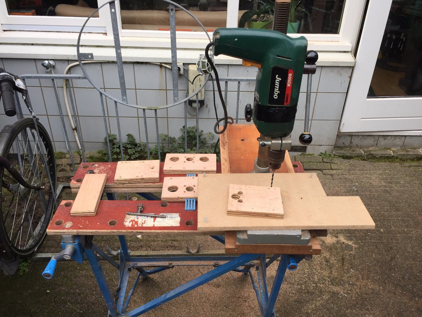

One of the most difficult part is the Z-block. Drilling of the holes has to be very precise, otherwise the friction will be too high, since the steel rods won't be perfectly aligned with the holes in the side panels of the x-assembly. My tip is to use a mitre saw to cut the wood and a drill press to make the holes! For the larger holes, I first used a drill press to make a start and then a router to make enough space.
All black parts in the design are 3d printed, since it's easier to gain high accuracy then. Those parts can be found on the thingiverse link from the previous step. The white thingies are the nylon bearings.
The wood needs to be sawn and drilled as shown in figure 2.
Step 6: Assemble All Hardware


Now start assembling all parts. Begin with the Z parts, then connect them to the X-frame. Then attach the bottom part of the x assembly and attach all to the Y-axises. The 3D printed Y-Nut, X-Nut and Z-Block parts have space for a nut that goes over the threaded rods. Use these!
After assembling, make sure that you can move each axis by turning the threaded rod by hand. If this is very difficult, your alignment is probably wrong, causing a lot of friction. Reassemble and realign until this is all good!
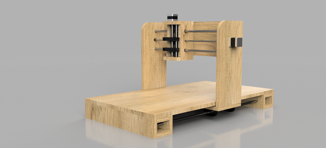
In the end, you should end up with the full assembly as shown in the second image.
Step 7: Motordrivers and Wiring


With the motor drivers I used, the wiring should be as shown in figure 1. The ground on the left of the image, is the ground from the arduino (not from the 12v power supply).
The Phase A and Phase B can be found using a simple multimeter: The resistance over a phase (A+ and A- for example) is zero. For the wiring, it doesn't matter which one is A+ or A-, as long as the resistance between both A wires, is zero. Same for the B phase.
The switches on the motor driver are not really clear to me yet, but with S3 and S4 switched in this way, the step size will be 1/8 of the normal step size, resulting is much more gentle and precise steps.
The wiring on the Arduino is as explained in the grbl wiki on Github. For the minimum basics, we only have to wire digital pins 2-7 and GND to the stepper driver boards.
Step 8: Flashing the Arduino

Download and extract GRBL from Github and open the Arduino IDE. Via Sketch -> Include Library -> Add zip library select the 'grbl' directory from the just extracted folder. Restart the arduino IDE and under file -> Examples, there should now be a grbl example, named grblUpload. Open it and upload it to the Arduino.
Now open the Serial monitor (under Tools) and set baudrate to 115200.
You should now get the message 'Grbl 0.9j ['$' for help]'
So enter $ and hit return. Now enter $$ and hit return. There you should see all the current settings for your grbl, which should be as default. Now, you can change everything you need. Details are explained on the grbl Github. My settings are as attached, but if your axis move in the wrong direction (because you might have B- and B+ different for example), you should switch these.
Step 9: The First Circle


When the building and the flashing is done, it's time to do something! Download the Universal G-Code Sender here (info on Github, here) and connect to your Arduino with a baudrate of 115200 again.
Now power up your power supply and go to 'Machine Control'. You should now be able to move your machine using the controls on this display!!
Hook up a pen to your z-axis, and save this text (using notepad) as circle.gcode:
G17 G20 G90 G94 G54
G0 Z0.25X-0.5 Y0.
Z0.1
G01 Z0. F5.
G02 X0. Y0.5 I0.5 J0. F2.5
X0.5 Y0. I0. J-0.5
X0. Y-0.5 I-0.5 J0.
X-0.5 Y0. I0. J0.5
G01 Z0.1 F5.
G00 X0. Y0. Z0.25
When you go to the File Mode tab in the Universal G Code Sender, you open circle.gcode and as soon as you click Send, your machine should now start painting a circles with a diameter of exact 2 inches!
Step 10: Finishing

As soon as you know your machine is working, it's time to hook up your router of dremel to start milling! Because every router is different from others, you have to be a bit creative yourself. But when you have come this far, I'm sure you'll get your router attached!
Good luck!
If you liked this instructable, please vote for me in the Arduino Contest. :)
Step 11: Update: Seeing It Work

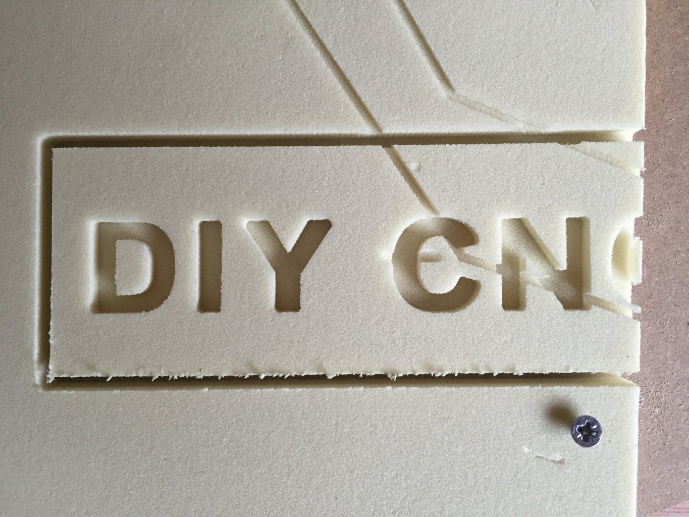
Ok, I was lacking some time this past week, but since I promised to show you guys some results, I did my best. I'm still figuring the CAM functions of Fusion 360 out, so as you can see in the images attached: The starting point of the sample was not correct, so that the final 'C' didn't fit. This had nothing to do with the machine, but with my abilities with Fusion 360.
As you can see: The finishing of hard foam is pretty good!
Note: The wooden piece is there to press the foam down. I didn't fix it too well, so it moved up a bit.
I'm very happy with the result so far!!
Step 12: After a Few Weeks
Ok, we're now a few weeks later. I tested some more and I'm very happy with the updated design.
Some facts:
- I can route hardwood-plywood at a federate of 400mm/min with a 6mm 4-flute router bit and a depth of 2mm per pass.
- I also tried the same feed-rate and same router with with a depth of 4mm per pass, but this caused the wood to burn because the friction was too high. The accuracy however, stayed acceptable, but I don't recommend this setting.
- Because I used threaded rods instead of leadscrews, I have some backlash on the y-axis. This results in flattened circles. I can probably tune this a bit by tweaking the nuts under the x-gantry, but I'll probably switch to lead screws in the future.
Like I said: I'm very happy with it! Now I need more projects to use it for. ;-)

First Prize in the
Arduino All The Things! Contest


