

Introduction: How to Use I2C in LabVIEW


For this project, I connected the PmodGYRO to the chipKIT WF32 using LabVIEW and LabVIEW MakerHub LINX. This guide will go through how to set up the pull-up resistors for successful I2C communication and how to read a data sheet to find what you need to correctly configure PmodGYRO and read the values.
Hopefully you can use this as a guide to code your own I2C devices using LabVIEW.
This project can be done using the LabVIEW Physical Computing Kit which contains LabVIEW Home Bundle and chipKIT WF32.
Step 1: Materials
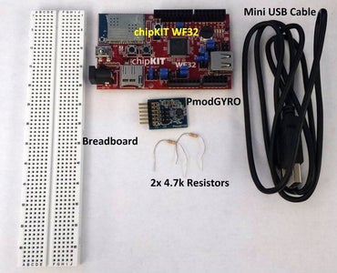
1) LabVIEW
LabVIEW Home Bundle can be used for this project and is sold by Digilent. Otherwise, any LabVIEW version can be used including the free trial.
2) chipKIT WF32
3) LabVIEW MakerHub LINX
Installation is free and in depth instructions and video guides can be found here to learn how to install and use LINX. Just click "Getting Started."
5) PmodGYRO
6) Two 4.7kΩ resistors
7) Breadboard (check out the "Solderless Breadboard Kit - Small" on this page here).
Step 2: Software Installation
If you have installed LabVIEW, chipKIT WF32 drivers, and LabVIEW MakerHub LINX already, you can skip this step.
First, install LabVIEW onto your computer.
Next, install NI VISA here if you did not include it in your LabVIEW installation. Once that is completed, install LabVIEW MakerHub LINX here by clicking on download now from the attached page. A detailed installation instruction video can be found by clicking on "Getting Started."
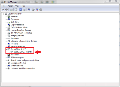
With all the required software installed, connect chipKIT WF32 to your PC using a USB A to mini B USB cable. Windows will most likely install the device drivers automatically. To make sure, open the device manager from the control panel and expand the Ports section. The COM port is the chipKIT WF32 and if the drivers were not installed correctly, a yellow exclamation mark will appear over the device.
If the drivers were not installed properly, download the drivers for your device which are included as part of MPIDE found at http://chipkit.net/started/install-chipkit-software/. Once the drivers are installed, right click on the COM port for the chipKIT WF32 and click properties then click on port settings and choose advanced. Under the BM options, change the latency timer to 1 ms.
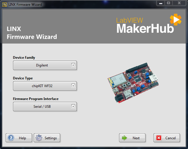
Now, launch LabVIEW and click tools --> MakerHub --> LINX --> LINX Firmware Wizard to deploy the LINX firmware to the chipKIT. Choose Digilent from device family and choose chipKIT WF32 from device type and click next (pictured above). Choose the COM port that the WF32 is connected to. Click next and then choose LINX serial/USB and click next again. The firmware will then be transferred to the WF32 and the on-board lights will flash.
Again, if you're having trouble with these steps, check out the guide on LabVIEW MakerHub for step-by-step video instructions.
Step 3: I2C Setup


The next step is to connect the PmodGYRO to chipKIT WF32 using pull-up resistors and a breadboard.
On the Pmod, the upper-most pin corresponds to SCL and, moving down the pins, SDA, GND, and then VDO. Connect the SCL and SDA lines to the breadboard so that you can connect a pull-up resistor from each line to 3.3V (more on this later). Connect the ground pin directly to the WF32 and connect the VDO pin to another place on the breadboard.
Take the 3.3V from the WF32 and connected that to the breadboard so that this will be in-line with the VDO and the Pmod will now receive power. From here, connect one 4.7kΩ resistor to the SCL line and 3.3V and connect the other 4.7kΩ resistor to the SDA line and 3.3V.
Now you should have VDO and GND connected to the WF32 and the SCL and SDA lines are individually pulled up to 3.3V but not yet connected to the WF32 directly.
Connect a wire from SCL to the analog 5 channel and connect a wire from SDA to the analog 4 channel.
Now you should have 3.3V and ground to the Pmod, and the SDA and SCL lines each have a 4.7kΩ resistor up to 3.3V and also a wire to analog 4 for SDA and analog 5 for SCL. This setup is pictured above (check the notes if you are confused).
Step 4: WF32 Setup
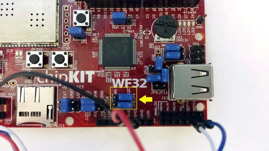
The next step is to move the JP4 and JP5 jumpers to I2C (pictured above). This turns the analog 4 and analog 5 channels into I2C SDA and SCL respectively.
Step 5: How to Read the Data Sheet and Code

Next, we need to view the data sheet for the gyro sensor. This will give us information about how the sensor works and what registers we need to read/write. The sensor the PmodGYRO uses is the L3G4200D and here is the data sheet for it. On page 10 there is information about the different resolutions for each of the ranges available. These will be important for converting the signed integer value into a meaningful value in degrees per second.
On page 22, the slave address is given as 110100xb. Since the SDO pin is connected to the voltage supply, the address is 1101001b which corresponds to 0x69 in hex or 105 in decimal. This page also details that if you want to read more than one byte at a time, you can auto-increment the data by placing a 1 in the MSb position. This will be important when reading from the data registers (more on this later).
On page 29, CTRL_REG1 0x20 is detailed. Here we can see what each bit means at that register. We want to put the device in normal mode and enable the x, y, and z axes so we need to write 00001111 to register 0x20. 00001111 is 0xF in hex so in labview we use an I2C write to register 0x20 and we write 0xF (the next entry in the array).
On page 32, CTRL_REG4 0x23 is detailed. We see that this is where we can set the full scale detection. For 250 dps, we need 00000000 (0x0), for 500 we need 00010000 (0x10), for 2000 dps we can put either 00100000 or 00110000 (I used 0x30). A case structure is used to write the correct hex value to this register depending on what range is selected.
There are other settings that you can mess with if you're interested in the control registers.
Now we need to figure out where the data is stored and how it is stored. On page 35 we can see that the values are stored from register 0x28 to register 0x2D (6 bytes of data, 2 for each axis) in 2's complement form. To read this, we need to point to the first register 0x28 with a 1 in the MSb place so the data can all be read at once (auto-increment). 0x28 with a 1 in the MSb place is 0xA8. Use I2C write to write this register and then use I2C read to read 6 bytes of data and store this in an array.
Next, the bytes are processed to give the values we want. Use index array to read individual entries and splice the x, y, z-axis data together. Multiply all of these signed 16 bit values by the resolution once they are converted to a 2's complement value since that is how the data sheet said these will be reported from the sensor.
Now do an I2C close and the hard part is done!
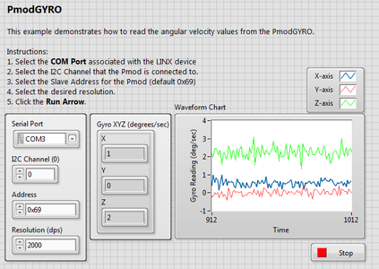
Step 6: LabVIEW Code
Below is the VI for the PmodGYRO. Download and open it. On the front panel, choose the serial port that you found earlier for the WF32 and select the address (0x69 in this case) and the scale you want. Click the run arrow and you're done!
Let me know if you have any questions.


