

Introduction: Motion Triggered DSLR Remote System


Behold, a long range motion triggered DSLR remote system! Build a device that automatically takes photos of moving objects when you're not around. It's the perfect standalone wildlife photography setup.
Hate Reading? Here's A Video:
A Brief Layman's Explanation:
The project is composed of two main units: the Motion Sensing Beacon and the Remote Receiver. Basically it's a one way communication system that utilizes an Arduino. The Motion Sensing Beacon is in charged of informing the Remote Receiver if motion has been detected. If the beacon does detect something, it will send a wireless go signal to the Remote Receiver (via RF). When the Remote Receiver receives the go signal, it will command the camera to take multiple shots thus capturing the object from a far. The Remote Receiver can also trigger multiple DSLRs within the reachable IR range, this means you can do the Matrix "bullet-time".The Remote Receiver kind of works as the middle man between the Motion Sensing Beacon and the camera. To sum it all up, this project is a long range motion triggered remote! :D
5 Useful Applications - Situations:
1.) Wildlife photography - set this up on an animal territory, leave it for a day. You'll get interesting shots!
2.) Marathons - automatically take photos of runners at a certain route or near the finish line.
3.) Sport Relays - One good example is swimming, swimmers travel at a straight path, this project can do the job.
4.) Home Security - Somebody steals cookies from you? It's about time to catch a photo of him.
5.) Pranks - Want to be discrete as possible? Take a burst of high-res photos instead of filming a crappy video! :D
... possibilities are endless!
Project In Action! (Here's a sample photo):
Step 1: Things You'll Need


Electronics:
- Arduino Uno (2x)
- 433mHz Serial Commmunication Module (TX - RX)
- USB PowerBank (2x)
- Motion Activated Infrared Alarm
- Solderless Prototyping Board (2x)
- Supply Of Jumper Cables
- USB Cables (for Arduino)
- 470 ohm 1/4w Resistor
- Infrared L.E.D.
- Hookup Wire
Tools:
- Soldering Iron
- Multitool
Step 2: Scavenge an IR LED


Why buy an IR LED if you can get one for free. If you have a very old TV/ Component/ DVD remote control you can dismantle it and snip off the IR LED.
Step 3: Find a Cheap RF Module (TX-RX)


In this project I used two Arduino boards rigged to a TX & RX module. I decided to use the 433mHz TX & RX since it's very cheap, discrete and stable. TX means transmitter and RX means Receiver. These wireless modules communicate via serial, sending data one bit at a time (@4800 bits/s). These tiny modules can communicate within a 200m radius. The range can be extended by adding an antenna.
Availability:
I bought mine from a local store named Alexan. Serial-com modules are difficult to find in local stores, it's a good thing that they are widely available online.
SparkFun:
The TX - RX module is available at SparkFun. They sell them separately. The TX module costs $3.95 and the RX module costs $4.95, both cost a total of $8.90.
DealExtreme:
So far the cheapest I've seen was form DealExtreme, they sell the TX - RX bundle for like $2.60 (w/ free shipping). I've tried one of these before, the quality is great, works as expected. I would recommend buying this product, just be weary that the package takes a month to arrive.
Extra Range:
 | These TX - RX modules have extra pins for an additional antenna. According to the book of "Practical Arduino" you can solder a 33cm long antenna on each module (TX & RX) would extend the range to +300m. Curling it helps making the project compact. |
Here's An Educational Video On Calculating The Antenna Legnth (by:Kevin Darrah):
Step 4: Find a Motion Activated Alarm


One of the main component that makes up this project is the Motion Activated module. Obviously it's a circuit that detects the presence of motion. These are called PIR motion sensors. PIR modules are a bit pricey that's why I decided to hack a dollar store door chime. These things are pretty common, I guess most local malls have these.
Arduino PIR Sensor:
If you want to buy the PIR sensor instead of doing the motion detection alarm mod (found at step#5), you can buy the PIR sensor from SparkFun ($9.95) or DealExtreme ($2.36). Just be sure you are knowledgeable enough on coding and on using the PIR sensor.
Step 5: Modify the Motion Activiated Alarm


Now it's time to modify Motion Activated Alarm in order for it to work with the Arduino.
Follow These Steps:
1st.) Disassemble the Alarm.
2nd.) Find a hookup wire.
3rd.) Drill a hole on the Alarms enclosure, large enough for the wire to fit through.
4th.) Insert the wire through the hole.
5th.) Desolder/ cut the wires from the speaker.
6th.) Solder the speakers wire to the hookup wire.
7th.) Solder the ends of the hookup wire on a 2 pin male header.
Notes:
Don't drill through the crowded area of the alarm to avoid hitting the components. In soldering the hookup wire, pay attention to the polarity.
Step 6: Build the Motion Sensing Beacon


The Beacon unit is in charge of detecting motion. It's composed of an Arduino, a RF transmitter module and a modified motion detection alarm.
Steps Of Assembly (checklist):
1st.) Grab a prototyping board, an Arduino, a RF transmitter (TX) module.
2nd.) Do a research on your RF transmitter's pin map.
3rd.) Mount your RF transmitter on your prototyping board.
4th.) Connect a jumper from the VCC of the RF transmitter to the 5v pin of the Arduino.
5th.) Connect a jumper from the ground of the RF transmitter to the ground pin of the Arduino.
6th.) Connect a jumper from the digital output of the RF transmitter to the digital pin# 12 of the Arduino.
7th.) Grab your recently modified motion detection alarm.
8th.) Connect the extended wire of the motion detection alarm to the breadboard.
9th.) Connect a jumper from the ground speaker output of the modified alarm to the ground pin of the Arduino.
10th.) Connect a jumper from the + speaker output of the modified alarm to the analog# 0 pin of the Arduino.
How It Works:
When motion is detected by the modified Alarm, the alarm releases pulses of voltage which makes the speaker whale. This means when the alarm detects presence, it gives off a + voltage output. By removing the speaker and tapping to its output, the arduino can identify analog signals given off by the alarm during detection. If the Arduino detects a presence of voltage from its analog pin (#0), it sends a go signal to the remote receiver's RX module. The signals are in forms of serial, the Arduino reads this as characters (alpha-numeric data). The characters are 1 and 0. 1 for a presence of motion and 0 for an absence of motion.
Step 7: Build the Remote Receiver (Middleman)


As mentioned in the intro step, the remote receiver acts as the middleman. How? When the remote receiver receives a go signal from the beacon, the remote receiver sends an IR signal to the DSLR, commanding it to take multiple shots.
Controlling A Remote Control With A Remote Control:
Why use an IR LED to command the camera? Why not hookup the remote receiver directly to the DLSR via cable? Isn't it stupid to control a remote control with another remote control? To others this seems to be a very stupid idea, but the truth is, it isn't.
The reason why I made the remote receiver act as an IR remote is because, I planned to use this on multiple cameras stationed closely together (pointing at different angles). A single IR LED can trigger multiple DSLR cameras within the reachable range. If ever you have plans on doing this, you won't have to build multiple receiver units, a single LED can solve the problem.
Steps On Building:
1st.) Grab a prototyping board, an Arduino, a RF receiver (RX) module.
2nd.) Do a research on your RF receiver's pin map.
3rd.) Mount your RF receiver on your prototyping board.
4th.) Connect a jumper from the VCC of the RF receiver to the 5v pin of the Arduino.
5th.) Connect a jumper from the ground of the RF receiver to the ground pin of the Arduino.
6th.) Connect a jumper from the digital input of the RF receiver to the digital pin# 12 of the Arduino.
7th.) Get your IR LED.
8th.) Connect the negative pin of the IR LED to the ground.
9th.) Connect a 470 ohm resistor to the positive pin of the LED.
10th.) Connect a jumper from the other end of the 470 ohm resistor to the digital pin# 11 of the Arduino.
Notes:
If it doesn't work, try to point a camera on the IR LED, the camera should be able to see the LED flash. BTW, our eyes could not perceive the infrared spectrum.
Step 8: Install the Arduino Libraries


I wanted to give emphasis on this step because from my past project a lot of people came to me complaining that the codes didn't work. Here's a lesson, Arduino codes beginning with the "#include " line indicates that the code requires certain library in order to work. This project requires an installation of additional libraries. There is a downloadable content below, containing the required library add-ons.
Steps In Installing Libraries:
1st.) Download the library pack.
2nd.) It's compressed in a ZIP, extract it.
3rd.) Copy the extracted files to the library folder of your Arduino program (ex. C:\Program Files (x86)\Arduino\libraries).
Attachments

Step 9: Upload the Arduino Codes


Obviously Arduinos need codes to work! :)) They are computers after all. Here are the codes for both the Remote Receiver and the Beacon. The remote receiver's code written in this page is for Nikon users only. Please download the code package below if you're using a different brand. Here are the supported/ compatible brands Canon, Minolta, Nikon, Olympus, Pentax, Sony. As for the beacon's code, compatibility is not an issue.
Beacon Unit (TX):
#include
char *controller;
void setup() {
pinMode(13,OUTPUT);
vw_set_ptt_inverted(true);
vw_set_tx_pin(12); vw_setup(4000);
}
void loop(){
if(analogRead(A0) > 500){ //You can add a for loop here to take multiple shots
controller="1";
vw_send((uint8_t *)controller, strlen(controller));
vw_wait_tx();
digitalWrite(13,1);
delay(10);
}
else {
controller="0";
vw_send((uint8_t *)controller, strlen(controller));
vw_wait_tx(); digitalWrite(13,0);
}
}
Remote Receiver (RX - Nikon):
#include
#include
Nikon D5000(11); // I Use Nikon (please use the code that works with your DSLR)
void setup() {
vw_set_ptt_inverted(true);
vw_set_rx_pin(12);
vw_setup(4000);
vw_rx_start();
unsigned int data = 0;
pinMode(13, OUTPUT);
pinMode(11, OUTPUT);
}
void loop() {
uint8_t buf[VW_MAX_MESSAGE_LEN];
uint8_t buflen = VW_MAX_MESSAGE_LEN;
if (vw_get_message(buf, &buflen)) {
if(buf[0]=='1') {
digitalWrite(13,1);
D5000.shutterNow();
}
if(buf[0]=='0') {
digitalWrite(13,0);
}
}
}
Attachments
Step 10: Power Them With Your Powerbanks

Want a tip? An Arduino doesn't always have to be connected to an AC adapter, to your computer or to a battery pack. They can also be powered with USB powerbanks! Now you can setup the project anywhere you like.
Step 11: Set Your Camera


You'll have to set your camera's settings in order for it to work with the system.
Option# 1:
Set your camera to the remote control mode then pre-focus on the area where the beacon is. This is the easiest between options although it may result to having unfocused images, specially when using a low "f" number. The advantage of this option is battery conservation. Your camera's battery would last longer by not using live view.
Option# 2:
Set your camera to the remote control. Use live view mode. Select AF-F (Full-Time-Servo). Select face priority or subject tracking. These settings would help you get a better consistency in getting focused images. The only disadvantage is the battery consumption. Live view consumes a lot of power, it will drain our battery faster.
Step 12: Go Out & Give It a Try


Get a tripod, attach your camera, keep the remote receiver close then position your beacon.
Step 13: Sit Back and Relax

Let the system do the job!
Step 14: You're Done! Enjoy!


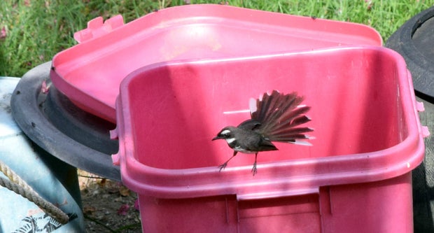
Here's what I got. In the first photo, the system was able to catch a photo of a bird, landing on the trash bin's ledge. I guess I cropped some of the photos too much.
______________________________________
Thank you for your time! I hope you guys enjoy this project! :D
Step 15: A More Permanent Setup

Here's my beacon, the Arduino, battery and receiver is packed inside the plastic enclosure. My next Motion Activated Remote project would probably become smaller, this time with a custom PCB! :D
Step 16: Please Vote! :D

If you like my project, please do not forget to vote! :D I really need a 3D printer for my projects.

Second Prize in the
Microcontroller Contest

Participated in the
Formlabs Contest

Participated in the
Tech Contest


![Tim's Mechanical Spider Leg [LU9685-20CU]](https://content.instructables.com/FFB/5R4I/LVKZ6G6R/FFB5R4ILVKZ6G6R.png?auto=webp&crop=1.2%3A1&frame=1&width=306)


