

Introduction: Motorized Correction Collar for Microscope Objective


In this instructable, you'll find a project involving an Arduino and 3D printing. I made it in order to control the correction collar of a microscope objective.
The goal of the project
Every project comes with a story, here it is: I am working on a confocal microscope and I am doing Fluorescence Correlation Spectroscopy measurements. But as this microscope is used with biological samples, some measurements have to be done at specific temperatures. So an opaque thermostated chamber has been made to keep the temperature stable. However, the objectives are no more accessible... And it is quite difficult to change the correction collar value of the objective.
Parts needed:
- An Arduino board. I have used an Arduino nano because it is smaller.
- A servomotor. I have used an SG90.
- A 10kOhm potentiometer.
- 3D printed pieces.
The steps:
- The objective: overview
- The objective: all the parts
- The objective: the gear teeth
- The objective: how to attach the gear?
- The controller: overview
- The controller: all the parts
- The controller: the Arduino circuit and code
- Conclusion & files
Before to start:
I have based this work on three different references:
- Concerning the technique: here is an article where the author was facing similar issues and developed a motorized objective. I have downloaded some parts he designed (the motor holder) and redesigned them to fit the objective.
- Concerning the Arduino holder: I have used this piece, I have downloaded it on Thingiverse and I have redesigned it.
- Concerning the code: I have used the same code proposed in the Arduino tutorial to control a servo-motor with a potentiometer. And I have modified it to fit perfectly with the gauge values.
And I have reshaped and modified all of these previous projects into one single project with new features:
- I have made easier attaches to fix the gears to the objective
- I have used gears with bigger teeth
- I have built a small gauge to change the values of the correction collar
- And I have made a small box to hold the Arduino board and the potentiometer
I also wanted this project to look like it is finished, but using no glue and no soldering, so the circuit can be fully reused easily. Therefore I have used jumper wires for the electronic connections, and M3 screws and nuts to attach the plastic parts together.
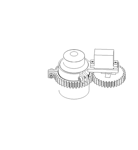
Step 1: The Objective: Overview

Here is just an image of the objective I am using, and the servomotor attached.
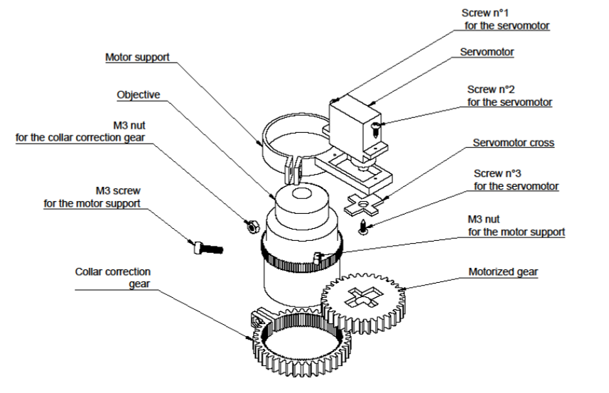
Step 2: The Objective: All the Parts
After the article Easy Exploded 3D Drawings of JON-A-TRON, I could not resist making my own gif and drawings.
Below you can see how the pieces are connected:
And on the image below the drawing with the nomenclature.
As you can see, the motor support was inspired and modified from this article . However, I have changed the way to attach it to the objective, and the gears module.
Also, note that the "servomotor cross" and the "motorized gear" are just assembled together without a screw.
Step 3: The Objective: the Gear Teeth

As you can see on the right of this picture, the original teeth of the objective gear were really small. I have tried to 3D print a gear with the same module, but of course, it does not work well... So I have made a ring gear to place on the gear of the objective. The inner part of the ring has small teeth to grip to the objective gear, while the outer part has bigger teeth.
Step 4: The Objective: How to Attach the Gear?

To attach the ring gear and the motor support to the objective, I have used a system similar to a hose clamp, with M3 screws and nuts. This way, the parts are strongly attached to the objective.
Step 5: The Controller: Overview


Here is the second part of the project: the controller. It is basically a plastic box containing the Arduino board, the potentiometer, and a gauge to choose the correct value of the correction collar.
Note that nothing has been glued, or soldered.
Step 6: The Controller: All the Parts
Again, below you can see how the parts are assembled.

On the image below, you can see that the M3 screws and nuts are used to hold the potentiometer, and close the box (attach the lower and upper parts of the box). And the M6 screws are used to fix the box on the optical table where the microscope stands.
The "gauge" part is the only piece that has been glued (to attach it to the "plastic box"), and I have used cyanoacrylate glue.

Step 7: The Controller: the Arduino Circuit and Code


Here is the code used to control the servomotor. It basically relates the potentiometer to the motor according to its values. You can find the code here.There is no need to write it if it already exists, however, it is important to understand how it works.
In this case, I have calibrated the device, so when the arrow is pointing at a value, the collar of the objective has the same value.
The line you might have to modify is the following.
val = map(val, 0, 1023, 0, 180);
The numbers "0, 1023" are related to the potentiometer values, while the numbers "0, 180" are related to the steps of the servomotor. To perfectly calibrate the device, I have changed these values until I was satisfied.
Step 8: Conclusion & Files
This is an easy project, but still quite interesting as it involves 3D printing and Arduino. Plus, it is very useful because we can control the correction collar of the objective without buying a new motorized objective (which can be quite expensive).
Thanks for reading! Feel free to comment if you have any suggestion!
Attachments


Participated in the
Make It Move Contest 2017


