

Introduction: Scrolling Bubble Display


Have you ever wanted to see you name written in bubbles?
Do you have an off-cut of roofing plastic that you don't know what to do with?
Do you prefer your text presented in a therapeutically slow and rattly way?
If you answered yes to any of these, well this is the project for you!
This instructable shows how to make a scrolling bubble message display powered by Arduino. It takes text sent over serial to the Arduino and displays it by writing the letters in bubbles.
This is made predominantly of plastic, comprising an off-cut of polycarbonate twin wall plastic roofing sheet for the screen with a polyethylene manifold and laser cut acrylic nozzle plate with plastic nozzles, and Tygon and nylon tubing, so please vote for me in the plastics contest.
To make this project you will need:
- Twin wall roofing polycarbonate sheet
- Silicone sealant
- An end plate (recommend laser cutting from acrylic, but 3D printing or hand making would work)
- An Arduino
- An airbrush compressor - preferably the type with a reservoir tank that automatically cuts in and out to avoid dead heading the compressor
- Normally closed solenoid valves - 1 per channel (I used 12)
- Means of switching the solenoids (MOSFETs would do but I used 3 Adafruit MotorShields* - they stack to work on one Arduino)
- Means of distributing compressed air to the valves (tubing and Y pieces work, but a manifold neatens things up considerably)
- Screw terminal power busbars for adjustably restricting each channel (probably optional)
- Soldering iron and solder
- Wire
- A computer to send text by serial over USB
Step 1: Twin Wall Channels and Nozzle Plate


The bubbler needs air injection points for each channel. I found a bag of assorted fluidic fittings being thrown out during the clear out at work, and in this there were some large (4ish mm) to small (2ish mm) barb threaded bulkhead fittings. These seemed ideal as bubble injector nozzles.
My first prototype scrolling bubble display was mounted around the circumference of a large cylindrical vase. I found however that the rising bubbles create convection currents that not only change the speed different bubbles rise, deforming the letters after time, but also these currents can draw in adjacent bubbles sideways, sometimes destroying the letter before it is even formed. I realised that the bubbles need to rise in channels to separate them and keep them under control. Initially I looked at getting several separate tubes, but this looked really expensive.
After a while I discovered twin wall polycarbonate roofing sheets. Twin wall is absolutely ideal as it is really cheap, very clear and you don’t have to attach any separate tubes together. The only challenge is sealing the base...
To do this I laser engraved the twin wall end shape into some 6mm acrylic to form deep channels (~3mm deep) such that it would fit neatly over the end of the twin wall. When the time came, adding silicone sealant in this channel and an extra bead of silicone around the outside created a perfect seal. But first the nozzles needed fitting... I laser cut holes for the nozzles while engraving the grooves and I tapped these out to 1/8 BSP to match the thread on the fittings. I also laser cut some laserable rubber (designed for making stamps) to use as a gasket to seal on the nozzles.
I imagine if you don't have a laser cutter, you could just use a simple piece of plastic... sanding the front surface and applying silicone sealant along the edges of the twin wall would probably achieve an adequate seal, and PTFE thread seal, sealing washers of cork or rubber, or thin o-rings could be used to seal the nozzles. 3D printing a fully dense part could also work as long as it is air tight, and you could even print a ninjaflex gasket. Choose the approach available to you!
Step 2: Air Supply and Solenoid Valves


I started using a pond air pump, which didn't have enough beans to supply the air. If multiple valves opened, water would rush into all but one! I then borrowed a small compressor, but it spent a lot of time supplying air to a dead end when not bubbling, which was not good for it, so I had to add a bleed path to ensure it had flow. With this it was struggling to keep a constant pressure for making bubbles. In addition it was also very loud.
To resolve these issues I bought an airbrush compressor with a reservoir tank. The compressor is nice and quiet and cuts in and out as required to maintain pressure in the tank. It also has a regulator to control the output air pressure, allowing much more consistent flow to the bubbler.
The high pressure air needs to be supplied in parallel to all 12 valves. Initially I did this with a collection of 'Y' barb fittings, creating a branching tree of valves, but this was chaotic when the output tubing and wiring for all 12 valves was added. To make matters worse, the valves I was using had been thrown out at work, presumably because the pressed in barb ports fall out really easily, meaning the tangle of valves was unreliable and every time a port fell out the water would drain onto my floor... not ideal. Fortunately I have a friend with a CNC mill, who machined a manifold out of an off-cut of polyethylene to supply air to all the valves. Again, laser cut rubber was used as a gasket. This manifold neatened up all the plumbing significantly and also allowed much more consistent and short length tubes between the valves and the nozzles. If you are wondering why 3 valves face the other way, they have different recommended port configurations as they are slightly different valves (2/2 rather than 3/2).
To balance the flow through the different valves, the tubes to the nozzles were passed through some large screw terminal power busbars, for screw adjustable pinch restrictors. This enabled fine adjustment that improved the letter shape consistency.
Step 3: Electronics


To drive the valves we need a controller to decide when to switch them on, for which I used an Arduino Uno. Because the valves draw more current than the Arduino outputs can give, we also need some power switching electronics to actually switch the current. The valves are quite small so these could be pretty much any transistor paired with a fly back diode to prevent damage from switching the inductive load, however I had just bought a box of reject I2C motor control boards that appear to be either an unmarked prototype or a clone of the excellent Adafruit Motor Control Shield*. These shields are great because they are individually addressable, so you can stack lots of them to control an almost limitless number of loads, and they contain all the fly back protection needed too.
If you go with Adafruit Motor Shields, you’ll need 3 for 12 channels. Solder the address jumpers so each shield is different, then wire each valve to a different motor output. Now stack the boards onto an Arduino and hook it up to a computer. You are probably best waiting until the board is programmed before connecting motor power connections to the motor shields, especially if like me your valves want 3V and you shields need 5V.
I recommend wiring the valves up in order to a long terminal block pair so that if something either comes loose or needs switching out, you can keep track easily. I found the valve wires were too small and kept coming loose so I crimped on bootlace ferrules to keep the better attached.
At this time I also added an LED strip into the spare channel in the twin wall at the top, so that the bubbles catch the light.
*I strongly recommend buying the genuine article, and generally try to avoid clones as they don’t support the designers, but at under £1 per board and only a single soldered jumper needed to make them work, I couldn’t resist getting a box of these rejects!
Step 4: Software


You can find my code here. If you are using the same Motor Shields and address them 60-62 it should work without modification. Otherwise, adjust it as necessary.
To give you a feel for how I wrote it:
I started by writing the code to drive the valves using the motor shields. I only ever use just over half speed so that the valves don’t get more than their rated 3V off the 5V supply.
I managed to get over my fear of pointers in order to define an array of valve channels to more easily reference the different channels by number.
I then made a ‘font’ of characters. These are stored as a series of two byte columns, where each pixel of each vertical column in the letter is a bit within the 2 bytes representing that column. 1 represents bubble needed, 0 is no bubble. Initially I started manually creating a ‘font’ using Matlab, but then I discovered a program that would directly output almost exactly what I was making. MikroElectronica GLCD Font Creator is freeware designed to make new fonts for LCD displays. It does seem to add an extra byte per letter, but I accounted for and ignored this and copied the ‘font’ block straight in as is. Note that GLCD Font Creator does not save anything when run on modern windows. You can however copy the relevant code out of the export window.
Fonts need to be stored in program memory, as the Arduino hasn’t got enough dynamic memory to hold it all.
I had to adjust the characters, especially when they have horizontal lines, because the compressibility of the adjacent bubble means more air is injected than expected, distorting the letter. I modified the characters so they come out about right. Adding restriction using the tuning screws also helped this.
I then made code to:
- Split two bytes into bits and command relevant valves to make bubbles
- Take a ‘char’ (ascii number relating to the character) and find the relevant two bytes from the font, and write them to bubbles
- Take a string and write each ‘char’ in turn
- Accept text over serial and write the string in bubbles
- I finally added a screen saver so it doesn’t sit there doing nothing when no one types
Step 5: Testing and Tuning
Now it’s time to fill the channels with water and start bubbling! Take care not to overfill the channels, I found if they were filled past half way, a long string of the wrong letters would cause an overflow. While this means there are only three letters on show at a time, this doesn’t really matter, as the bubbles of subsequent letters distort the previous letters such that you can only really read the last 2-3 letters anyway!
Start by sending ‘|’ repeatedly. This should all float up in a line of relatively similar sized bubbles. If not, adjust the restrictor screws. Bare in mind that it is unlikely to be perfect, because firing all the valves at once causes disturbances to the pressure supply. Next, Type in lots of slashes with spaces ‘/ / / / / /‘; staggering the release should give even better bubble consistency.
Hopefully you can now type text and read it in bubbles!
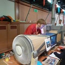
Step 6: Finished Product!
We exhibited the scrolling bubble display at Derby MakerFaire, where it was very well received.
We set up a laptop with the Arduino serial window open, connected a wireless keyboard and let people type what they wanted*. The vast majority of people either went for ‘Hello’ or their name. Who new that Tyler is apparently one of the most popular names in Derby these days?
Anyway it was generally well received by both children and adults. If you’ve enjoyed this instructable, please vote for me in the plastics contest!
*Naturally there are some people who take the opportunity to write offensive messages, but they had astonishingly bad luck with connectivity dropouts on the keyboard - possibly because I’d have pulled the dongle for the keyboard out** ;)
**There was a range from wholly abusive to just quite cheekily rude which I of course let through... I was particularly amused by all the little boys who would write ‘poo’ just to provoke their mums. One mum even corrected her 7 year old “There are two Es in the ‘wee’ that you’re trying to type!”

Grand Prize in the
Plastics Contest


