

Introduction: Smart Blind Stick


People with complete blindness or low vision often have a difficult time self-navigating in outside environments. In fact, physical movement is one of the biggest challenges for blind people, explains World Access for the Blind. Traveling or simply walking down a crowded street may pose great difficulty. Because of this, many people with low vision will bring a sighted friend or family member to help navigate unknown environments. This project is a solution to this navigation issue. It consists of a blind stick which is equipped with ultrasonic sensors and pager motors. The stick scans for obstacles (people) and when found, it points a light in the same direction of the obstacle. Additionally, the pager motor vibrates if there is there is an obstacle that is approaching the blind person at relatively faster speed. This would help a blind person understand where the obstacle is and also its direction.
Step 1: Components Required
- Arduino UNO R3 x 1
- USB Cable x 1
- Ultrasonic sensor(SR04) x 2
- Pager motor x 2
- LED x 2
- Small PCB x 1
- Battery pack x 1
- Male to female connecting wires x 20
- Male to Male connecting wires x 20
Step 2: Connecting Ultrasonic Sensors With Arduino

Ultrasonic Sensor SR -04:
An Ultrasonic sensor is a device that can measure the distance to an object by using sound waves. It measures distance by sending out a sound wave at a specific frequency and listening for that sound wave to bounce back. By recording the elapsed time between the sound wave being generated and the sound wave bouncing back, it is possible to calculate the distance between the sonar sensor and the object.
Pin Configuration:
- VCC: 5V DC power supply.
- Trig: trigger signal for starting the transmission with 10μs high time.
- Echo: output.
- GND: ground
Calculating the distance of an object from Ultrasonic sensor:
Since it is known that sound travels through air at about 344 m/s (1129 ft/s), you can take the time for the sound wave to return and multiply it by 344 meters (or 1129 feet) to find the total round-trip distance of the sound wave. Round-trip means that the sound wave travelled 2 times the distance to the object before it was detected by the sensor; it includes the 'trip' from the ultrasonic sensor to the object and the 'trip' from the object to the Ultrasonic sensor (after the sound wave bounced off the object). To find the distance to the object, simply divide the round-trip distance in half.
Circuit Connections:
- Connect the ultrasonic sensor (front) Trig pin to the digital pin 9 on the Arduino using male to female connecting wire.
- Connect the ultrasonic sensor (front) Echo pin to the digital pin 10 on the Arduino using male to female connecting wire.
- Connect the ultrasonic sensor (right) Trig pin to the digital pin 6 on the Arduino using male to female connecting wire.
- Connect the ultrasonic sensor (right) Echo pin to the digital pin 7 on the Arduino using male to female connecting wire.
- Take a male to male wire, connect 1 terminal to the 5V pin on the Arduino and the other terminal of the wire to the breadboard.
- Take 2 male to female wire, connect the female terminal on the +5V pin of the ultrasonic sensors and the male terminal of the wires to the breadboard where you have connected 5V of Arduino.
- Take a male to male wire, connect 1 terminal to the GND pin on the Arduino and the other terminal of the wire to the breadboard.
- Take 2 male to female wires, connect the female terminal on the GND pin of the ultrasonic sensors and the male terminal of the wires to the breadboard where you have connected GND of Arduino.
Step 3: LED Interfacing With the Arduino

LED
LED is Light emitting diode. The main function of Diode is that it allows the current to flow in one direction only.
The LED has two terminals:
1. Positive Terminal: The longer leg of the LED is positive.
2. Negative Terminal: The shorter leg of the LED is negative.
Circuit Connections:
- Connect the positive terminal of LED (front) to Digital pin no. 11 of your Arduino.
- Connect the positive terminal of LED (right) to Digital pin no. 12 of your Arduino.
- Connect the Negative terminal of LEDs to 470ohm Resistors.
- Connect the remaining terminal of resistor to the GND of Arduino on Breadboard as shown in the figure.
Step 4: Interfacing Pager Motor With Arduino

Pager Motor(vibrator):
The cylinder shape is also called bar-type vibration motor. This vibrating motor is essentially a motor that is improperly balanced. In other words, there is an off-centered weight attached to the motor's rotational shaft that produces a centrifugal force while rotating. This unbalanced force displaces the motor. Its high speed displacement makes the motor to wobble, which is known as the “vibrating”. The wobble can be changed by the weight mass you attach, the weight's distance to the shaft, and the speed at which the motor spins.Motors work through a process called induction. When you an put electric charge through wire, a magnetic field is created. A coiled wire will create a stronger field, as will increased current.
PN2222A Transistor:
The 2N2222, also identified as PN2222, is a transistor bipolar NPN low - power general use.It serves both amplification and switching applications. It can amplify small currents at small or medium voltages; Therefore, it can only treat low powers (no more than half Watt). It can work at medium high frequencies. A PN2222A with its Collector, Emitter and Base identified by the letters ‘c’,’e’ and ‘b’ respectively.
Circuit Connections:
- Connect the transistor (front) base to the digital pin 4 on the Arduino using male to female connecting wire.
- Connect another transistor (right) base to the digital pin 5 on the Arduino using male to female connecting wire.
- Connect the emitter of the transistors to the negative terminal of the pager motors using male to female connecting wire.
- Take 2 male to female wires and connect the collector of both the transistors to the Breadboard where the GND of Arduino is connected.
- Take 2 male to female wires, connect one terminal to the positive terminals of the pager motors and the male terminal of the wires to the breadboard where 5V of Arduino is connected.
Step 5: Upload the Arduino Sketch
Attachments

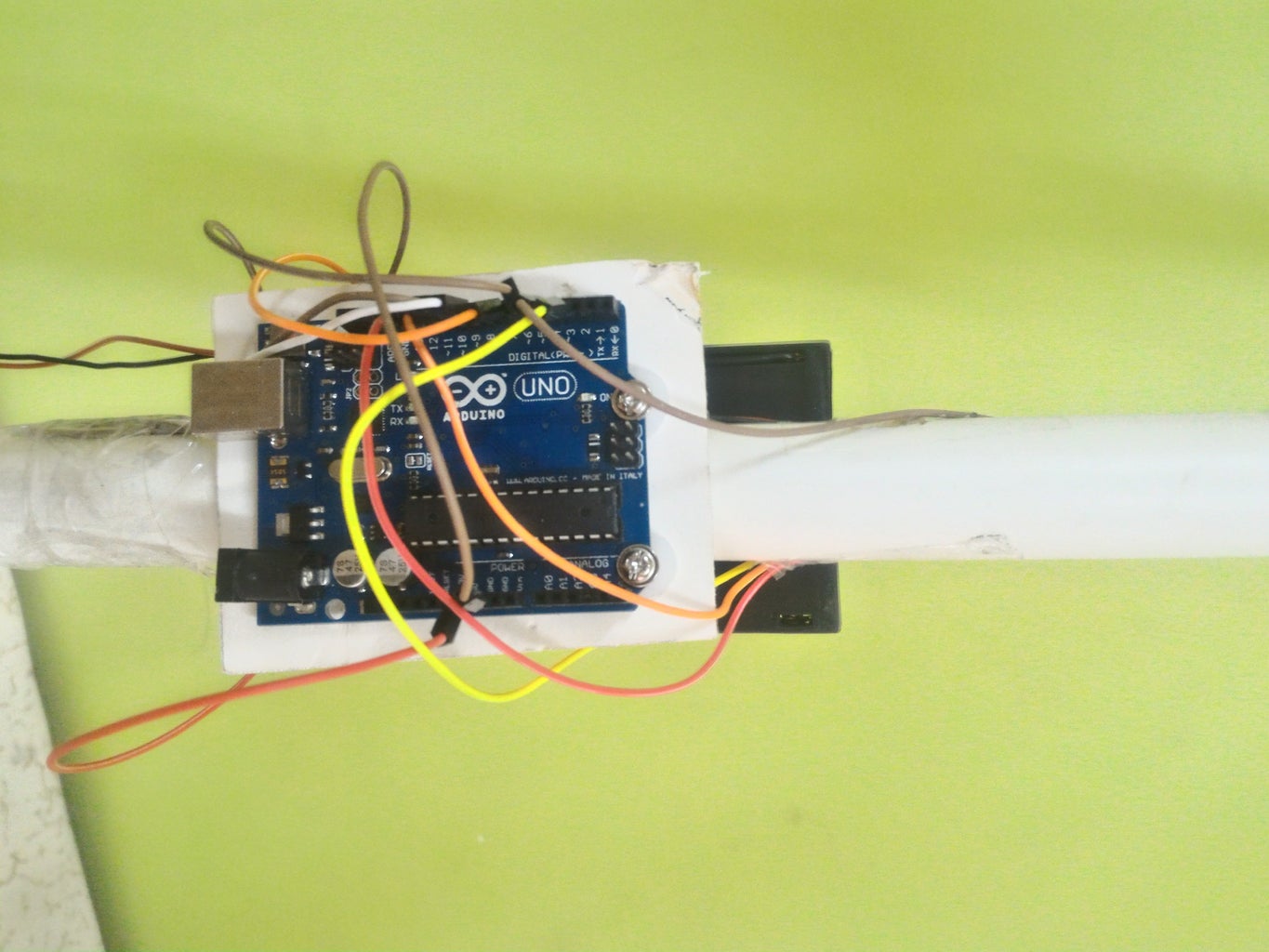
Step 6: Reference Images for Construction


![Tim's Mechanical Spider Leg [LU9685-20CU]](https://content.instructables.com/FFB/5R4I/LVKZ6G6R/FFB5R4ILVKZ6G6R.png?auto=webp&crop=1.2%3A1&frame=1&width=306)


