

Introduction: Smart Car Beam System


Night drive becomes dangerous especially when the high beam of an incoming car distorts the driver's vision. This project is aimed at automatically switching off the high beam of a car when the car senses an incoming vehicle. In the absence of the incoming vehicle, the high beam is switch on. The sensing of the incoming vehicle is accomplished with a simple Light Dependent Resistor.
Step 1: Car 1: Components Required
- Intel Galileo Gen1 x 1
- USB cable x 1
- Power cord x 1
- 1 Kohm resistor x 1
- LDR x 1
- LEDs x4
- 470ohm resistor x 4
- M-M Jumper wires x 20
- M-F Jumper wires x 20
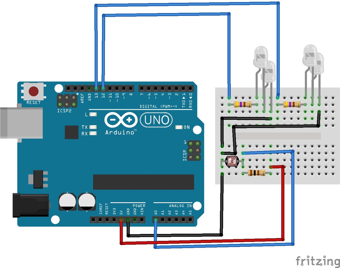
Step 2: Connecting LDR Sensor With Intel Galileo

LDR
LDR is expanded as Light Dependent Resistor. Depending upon the intensity of light projected to the surface of an LDR, it changes its resistance value. The value of resistance changes from few ohms under sufficient light condition to few Mega Ohms under dark conditions.
Circuit Connections:
- Connect one leg of the LDR to VCC (5V) on the Intel Galileo.
- Connect the other terminal of the LDR to the Analog pin 0 (A0) on the Intel Galileo.
- A 1Kohms resistor is also connected to one terminal of LDR which is connected to pin A0 as shown in the figure.
- The other terminal of resistor is connected to the ground of an Intel Galileo.
Step 3: Connecting the LEDs to the Intel Galileo
LED:
LED is Light emitting diode. The main function of Diode is that it allows the current to flow in one direction only.
The LED has two terminals:
- Positive Terminal: The longer leg of the LED is positive
- Negative Terminal: The shorter leg of the LED is negative
Circuit Connections:
- Connect the negative terminal of LED1 to the positive Terminal of LED 2.
- Connect one terminal of 470 ohm resistor to the positive terminal of LED1 and the remaining terminal of resistor to Pin no.13 on your Intel Galileo board.
- Now connect the negative terminal of the LED2 to the ground of your Intel Galileo Board.
- Similarly do the same for the other two LEDs (LED3 and LED4). Connect the resistor(470 ohm) to Pin no. 12 of the Intel Galileo board.
Step 4: Upload the Arduino Sketch
Attachments

Step 5: Car 2: Components Required
- 470ohm resistor x 1
- LEDs x 4
- PCB x 1
- 9V Battery x 1
- 9V Battery Connector x 1
- Toggle Switch x 1
- Soldering Kit x 1
Step 6: Circuit Layout for PCB Soldering

- Connect 4 LEDs in parallel configuration.
- Connect the negative terminal of the LED to the negative of the 9V battery
- Connect the positive terminal of the LED to one terminal of the 470ohm resistor.
- Connect the other end of the resistor to one of the end pins of the toggle switch.
- Connect the positive of the 9V battery to the middle pin of the toggle switch.
Step 7: Reference Images for Construction


![Tim's Mechanical Spider Leg [LU9685-20CU]](https://content.instructables.com/FFB/5R4I/LVKZ6G6R/FFB5R4ILVKZ6G6R.png?auto=webp&crop=1.2%3A1&frame=1&width=306)


