

Introduction: Waterproof Ultrasonic Sensor Module (JSN SR04T - 2.0) || Arduino
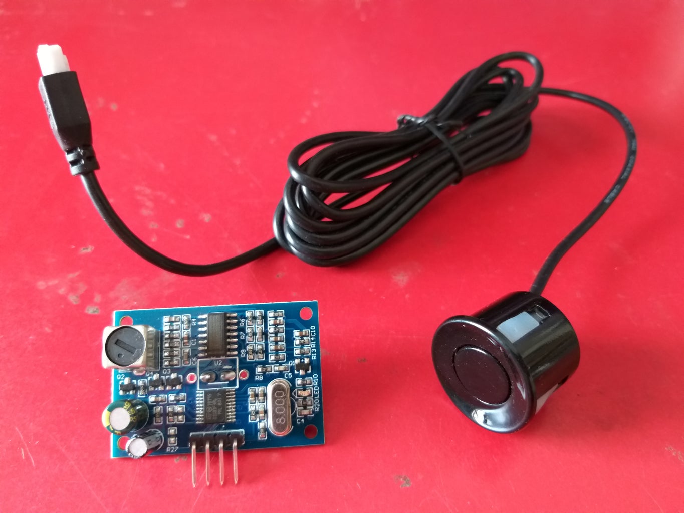


In this instructable, I will show you how to interface a Waterproof Ultrasonic Sensor Module (JSN SR04T - 2.0) with the Arduino board.
JSN-SR0T4-2.0 ultrasonic distance measurement module can provide 20cm-600cm non-contact distance sensing function, ranging accuracy up to 2mm; module includes the transceiver of an integrated ultrasonic sensor and control circuit.
Features:
- Small size, easy to use.
- Low voltage, low power consumption.
- High precision measurement.
- Strong anti-interference.
- Integrated closed waterproof cable probe, suitable for wet, bad measurement occasions.
Step 1: Ultrasonic Sensor (JSN SR04T-2.0) Specifications

Step 2: Operating Mode 1:

The basic working principle:
- Using IO port TRIG trigger range, to a minimum of the 10us high letter.
- The module automatically send 8 40khz square waves, automatically detect whether there is a signal to return;
- A signal to return, through the IO port ECHO output a high level, high time is the duration of ultrasound from the launch to the return time.
- Test distance = (high time * speed of sound (340 m/s)) / 2.
- The module is triggered after the distance measurement, if you cannot receive the echo (the reason exceeds the measured range or the probe is not on the measured object), ECHO port will automatically become low after 60 ms, marking the end of the measurement, whether successful or not.
- LED indicator, LED non-power indicator, it will receive the signal after the module will be lit, then the module is working.
Note:
R27 = open that is not solder.
Step 3: Operating Mode 2 (Serial Data, R27 = 47K Resistor.):
Serial output format for the TTL level, that: 100 ms module for the cycle of automatic transmission The value of the distance, in mm.
Serial baud rate: 9600, n, 8,1. Module power recognition, directly into the work mode, the module to conduct a distance every 100ms range and outputs one frame from the pin TX with four 8-bit data.
The frame format is: 0XFF + HIGH DATA + LOW DATA + SUM 1.
- 0XFF: for a frame to start the data
- HIGH DATA: the upper 8 bits of the distance data
- LOW DATA: the lower 8 bits of the distance data
- SUM 1: data and, for the effect of its 0XFF + HIGH DATA + LOW DATA = SUM (only low 8)
- HIGH DATA and LOW DATA synthesize 16-bit data, that is, the distance in millimeters.
Note: Mode 2: R27 = 47K resistor.
Step 4: Operating Mode 3 (Serial Data, R27 = 120K Resistor):
When the module power recognizes, the module into the standby state, the serial output format for the TTL level, the serial port baud rate: 9600, n, 8, 1.
When the RX port receives the 0X55 instruction, the module starts a ranging and outputs from the pin TX out of a frame with four 8-bit data.
The frame format is: 0XFF + HIGH DATA + LOW DATA + SUM 1.
- 0XFF: for a frame to start the data
- HIGH DATA: the upper 8 bits of the distance data
- LOW DATA: the lower 8 bits of the distance data
- SUM 1: data and, for the effect of its 0XFF + HIGH DATA + LOW DATA = SUM (only low 8)
- HIGH DATA and LOW DATA synthesize 16-bit data, that is, the distance in millimeters
Note: Mode 3: R27 = 120K resistor.
Step 5: Arduino Coding for Waterproof Ultrasonic Sensor (JSN SR04T - 2.0)
#define TRIGGER_PIN 13
#define ECHO_PIN 12
#define USONIC_DIV 58.0
#define MEASURE_SAMPLE_DELAY 5
#define MEASURE_SAMPLES 20
#define MEASURE_DELAY 25
void setup()
{
Serial.begin(9600); // Serial monitoring
pinMode(TRIGGER_PIN, OUTPUT); // Initializing Trigger Output and Echo Input
pinMode(ECHO_PIN, INPUT);
digitalWrite(TRIGGER_PIN, LOW); // Reset the trigger pin and wait a half a second
delayMicroseconds(500);
}
void loop()
{
delay(MEASURE_DELAY);
long distance = measure();
Serial.print("Distance: ");
Serial.print(distance + 22);
Serial.println(" mm");
}
long measure()
{
long measureSum = 0;
for (int i = 0; i < MEASURE_SAMPLES; i++)
{
delay(MEASURE_SAMPLE_DELAY);
measureSum += singleMeasurement();
}
return measureSum / MEASURE_SAMPLES;
}
long singleMeasurement()
{
long duration = 0; // Measure: Put up Trigger...
digitalWrite(TRIGGER_PIN, HIGH); // Wait for 11 µs ...
delayMicroseconds(11); // Put the trigger down ...
digitalWrite(TRIGGER_PIN, LOW); // Wait for the echo ...
duration = pulseIn(ECHO_PIN, HIGH);
return (long) (((float) duration / USONIC_DIV) * 10.0);
}


