

Introduction: Adjustable Toolpost for Taig Lathe


I bought a Taig lathe recently and am quite happy with it. However, some of the accessories are rudimentary so I like to make some modifications so that it is more user friendly.
My first idea is to remake the toolpost. The simple Taig toolpost is actually quite handy to use. It locks onto the cross-slide with a long cap screw through the body, secured with a square nut slid into either T-slot on the slide. Changing tool bits is easy, just release two cap screws.
Although Taig accepts imperial 1/4" bits, tool bits come also in different sizes say metric 6 mm or other under or oversized shanks. Also, as a worn bit is reground, the nose gradually drops below shank height. Getting the bit on centre requires precise shimming which is tedious, with each separate tool probably requiring a different shim. What I need is a toolpost which is just as simple to use but can be continuously adjusted for height.
I am inspired by some of the QCTP designs posted on YouTube. However I only have a home DIY shop. I don't have any sophisticated or professional equipment such as milling machine, shaper, surface grinder etc. and I don't have a big cross slide and a long lathe bed to accept anything but a small attachment. I have to use what I have, a bare bones mini lathe, a drill press, a bench grinder, an angle grinder and some hand tools.
Taig is made in the USA and all its parts are in imperial units. However I find it more convenient and less confusing to work in metric. So dimensions here are in metric units unless for the sake of consistency with the manufacturer's dimensions imperial sizes are indicated.
Some of the photos do not show the final appearance of the modified toolpost. I had to improvise and make minor changes as I went along and did not have the luxury of retaking some of the photos.
Step 1: The Design

This adjustable toolpost is made up of three parts, namely a vertical cylindrical shaft resting on a base, a modified factory made toolpost which slides onto the shaft and locked into place, and a screw and pin arrangement for height adjustment.
1. The factory made toolpost is made from a block of alloyed aluminium. This material, though reasonably hard, is easy to machine. It is first shortened by cutting half an inch off the bottom. This becomes the new tool holder.
2. An enlarged through hole is drilled into the tool holder to accept a sturdy steel shaft of the same diameter. This shaft is centre-drilled through to mount onto the cross-slide using the existing long cap screw. The centre of this new through hole is offset by several millimetres towards one corner of the toolpost block. This is necessary so that the enlarged hole will not cut into the tool slot which would otherwise interfere with proper tool seating, and to provide room for a height adjustment screw. The shaft is also made as thick as possible, given the constraints of the dimensions of the body, to provide maximum rigidity.
3. The tool holder slides up and down the shaft to adjust for height, and is locked in place with two set screws.
4. A pin-and-flange is fabricated at the lower end of the central shaft. This rests on a mating socket in a base forming a friction bearing allowing the shaft to rotate. A short key is screwed onto the underside of the base engaging the neck of the T-slot so as to stop it from turning when the locking screw is loosened.
5. Height adjustment is made by means of a screw on top of the tool holder. As the screw is turned, it raises or lowers the body. To avoid using an excessively long screw, only the upper one third of the hole is tapped. A short screw pushing against a steel pin makes up the length required.
6. Without the need for shimming, any tool bit with a shank thickness between 5 mm and 8 mm may be used on this modified toolpost. The maximum size is limited by the height of the tool slot of the original toolpost.
7. Only one size of cap and set screws, #10-32 is used throughout, so that it is not necessary to carry more than one size of hex key.
Step 2: Making the Shaft


I have a friend who owns a car repair garage and I sometimes forage his junk box for useful items of steel and aluminium. I found a few engine mounting bolts. These are made of toughened steel and have the right size for turning into the shaft for the new toolpost. You don't have to find a similar bolt. You can use a tough steel rod of the right size.
Putting this piece of scavenged bolt in my Taig lathe, I turned the bolt head down to 16 mm in diameter, I then turned the flange of the bolt head to 25 mm. The flange has a thickness of about 2.5 mm.
I turned the threaded part of the bolt down to a cylinder of 12.5 mm. This forms the stem of the shaft and fits snugly but not tightly in a 12.7 mm (half inch) hole which I would bore into the tool holder body later.
I trued both faces of the flange, reducing its thickness to about 2.2 mm. None of the above dimensions is critical. Later on, the socket in the base plate into which the shaft will mate will be bored to fit.
I drilled a 5 mm hole down the centre of the shaft. This will accept the #10-32 long cap screw which locks the toolpost down onto the cross slide. Since the steel bolt is made of toughened material, I have to use a low rotation speed and very shallow feeds, backing out the drill frequently to clear the chips and generously lubricating the bit from time to time.
The shaft is then cut off at 42 mm from the flange. At the other end I widened the central through hole to 8 mm to a depth of 12 mm using an endmill of the same size. This allows the head of the lock screw to be recessed and concealed within the shaft.
Step 3: Making the Base


The base is drilled with a stepped hole, forming a socket mating with the pin-and-flange part of the shaft. It augments the rigidity of the shaft when it is locked onto the cross slide, at the same time acting as a friction bearing allowing it to turn freely when the locking screw is loosened.
I cut a small piece of mild steel some 32 mm square, 8 mm thick. I squared off all six faces on the lathe using the four-jaw chuck and trimmed it finally to 30 mm square. After facing, the thickness is reduced to about 7 mm. These dimensions are not critical.
A 16 mm diameter hole is bored through the face of the base. Then a concentric 25 mm wider hole is bored on top to the depth of 2.2 mm, forming a stepped hole. This stepped hole should mate snugly with the pin-and-flange of the shaft. I tweeked the diameters of the shaft pin and flange to ensure that the shaft turns easily.
I then trimmed the height of the pin on the bottom end of the shaft to be 0.5 mm shy of the bottom of the base when the shaft is mated. This makes sure that when the locking screw is tightened, the shaft flange will first engage the base and clamp it down tightly before the bottom of the pin hits the surface of the cross slide.
I ground away the head of a small #10-32 screw on two opposite sides until it fits the neck of the T-slot on the cross slide. This is secured in a tapped hole on the bottom of the base. This screw keeps the base from turning when the locking screw in the shaft is loosened for repositioning or changing the tool angle.
Step 4: Modifying the Tool Holder


The tool holder is modified from the factory made toolpost.
Firstly, 13 mm is cut off from the bottom, reducing its height from 45 mm to 32 mm.
Asuming that you are looking at the tool holder from the side with the tool slot on the left, then the side facing towards you is the NEAR face, the side away from you is the REAR face, the side with tool slot is the LEFT face and the remaining side is the RIGHT face.
A 12.7 mm (half inch) hole is drilled through the tool holder from top to bottom replacing the existing hole. The centre of this larger hole is offset from centre by 1.5 mm to the far face, and 1.5 mm to the right face, or 14 mm from the left face and 14 mm from the near face. Since this new hole is not coaxial with the existing hole, it is not possible to drill it directly without the drill bit flexing and wandering into the existing hole. To overcome this, I secured the tool holder in the four-jaw chuck and used a 6 mm endmill to bore a pilot hole at the intended position. This is then widened with a 8 mm endmill, and finally, a 12.7 mm drill bit to full size. This way, the hole is bored perfectly to size and position.
Two holes tapped for #10-32 are drilled in the right face of the holder, aligned with the centreline of the vertical shaft. Set screws (or cap screws in the meantime) will be inserted here to lock the holder onto the shaft. Because the shaft is made from toughened steel, set screws do not deform or indent its surface, so that the tool holder can always smoothly slide up and down along it even after repeated tightening.
A 3.15 mm (1/8") through hole is then drilled at 4 mm from the right face and 4 mm from the near face. This hole is tapped #10-32 from the top of the tool holder to a depth of 12 mm. It accepts a 5/8" long #10-32 cap screw which is used to adjust the height of the tool. A 3 mm pin is cut to 20 mm. This pin is put aside for the time being and will be inserted into the lower part of the hole when the item is assembled and mounted.
Step 5: Assembly


I slid the tool holder onto the shaft and temporarily lock it in place with the set screws on its side. I secured a suitable tool bit in the tool slot with the two cap screws as originally intended.
I inserted the long #10-32 cap screw (locking screw) into the shaft from the top. I then placed the shaft onto the base and loosely screwed the square locking nut onto the end of this screw.
I inserted the 3 mm steel pin into the height adjustment hole from the top of the tool holder, and then screwed in a #10-32 5/8" cap screw (adjustment screw) from the top.
I finally slid the new assembled toolpost into one of the T-slots of the cross slide and locked it at a desired position.
To adjust for centre height the tool holder body is unlocked from the shaft by loosening the two set screws. Turning the adjustment screw against the pin further down the hole changes the height, clockwise to raise and counter-clockwise to lower. When the desired height is reached, the set screws are tightened. The back toolpost sold by Taig has the lower edge of the tool slot milled at lathe centre height, so I use it as a handy and accurate guide for adjustment.
The cutting angle of the tool bit can be changed easily without affecting its preset height. Loosening the long locking screw in the shaft allows the shaft and attached tool holder to rotate in its base socket to the angle desired. Tightening the locking screw again will secure it in place.
Step 6: Conclusion

I made this adjustable toolpost in just a day without using any sophisticated equipment. I used the factory supplied toolpost and modified it. I used recycled materials whenever I could, costing me practically nothing.
Since this is made for functionality and not for appearance, I have little concern for cosmetic imperfection and do not bother to polish surfaces to an appealing finish.
Putting the modified toolpost onto the cross slide, I find it to be just as rigid as the unmodified one, very easy to change tool bits, adjust centre height without shimming, or adjust tool angle. It also allows me to easily swap in a set of 8 mm bits which I have bought earlier at a garage sale.
I find this project to be the perfect first DIY job on my new lathe!
Step 7: Epilog - Further Improvements


Since writing this Instructable I have made further improvements. These are nice to implement but not essential. I made a new lock-screw from a 5 mm mild steel rod. The square nut at the bottom end is permanently tightened onto the thread. A 12 mm round handle nut screws onto its top. The handle nut is drilled and tapped #10-32 on one side angled up by 15° above horizontal to accept a 4.5 mm x 50 mm steel rod which is threaded to size. This rod serves as a handle to tighten the lock-screw. All the rods are salvaged from a laser printer from a neighbour's garbage bin.
I also replaced the height adjustment cap screw with a length of #10-32 thread attached to a brass knurl nut which are held together with locktite. I put a small spring under this knurled screw to prevent it from rattling loose under vibration.
With these modifications, I no longer need to get a hex key to reposition the toolpost or change the tool bit angle. I still need to loosen the two set screws with a hex key, and then twist the knurl nut by hand to adjust for height, but this infrequent adjustment is only neccessary if I change the tool.
I have not included these improvements as part of this Instructable since they are quite easy to implement and there are no critical steps to follow.
{20181231}
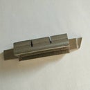
The screwed on index at the bottom of the base has been removed and replaced with an angle clip screwed onto the same position on the side. The clip retains the base connected to the tool post when dismounted from the cross slide, keeping the assembly as one integral tool. (see photos above)


