

Introduction: 'Arduino' Decision 'Box' BE (Attiny85)


Pleace notice: This project neither contains a box nor any Arduino* code.
I stuck with this name because this project is a modifictaion of Victor8o5's "Arduino decision box 2.0 (Attiny85)" posted three days ago. I liked the way it looks and works, but I also knew there's still room for improvements within the code, especially to reduce power consumption. I had some spare time so I thought I'd give it a go!
And this is the result, the "'Ardiono' Decision 'Box' BE (Breadboard Edition)". It's not nearly as fancy as the original version (or version 2.0), but it's enough to get a platform to optimize the code. So if you're serious about this project, head over to Victor8o5 for his version, my code is fully pin-compatible and thus exchangeable. This project took me no longer than three days from idea to finished instructable, so please be aware that minor bugs may still exist.
Have fun!
Contents:
- Hardware Modifications
- Features
- Ultra Low Power Design
- Final Words
*NOTE: The Attiny85 is Arduino compatible, but I'm more familiar with native C, so I decided to program the Attiny with that. If you just want it to work it's not different from flashing a .hex file containing Arduino code. Minor changes should also be fairly simple as almost every line is commented. If you encounter any issues, feel free to ask for help.

Step 1: Original Style
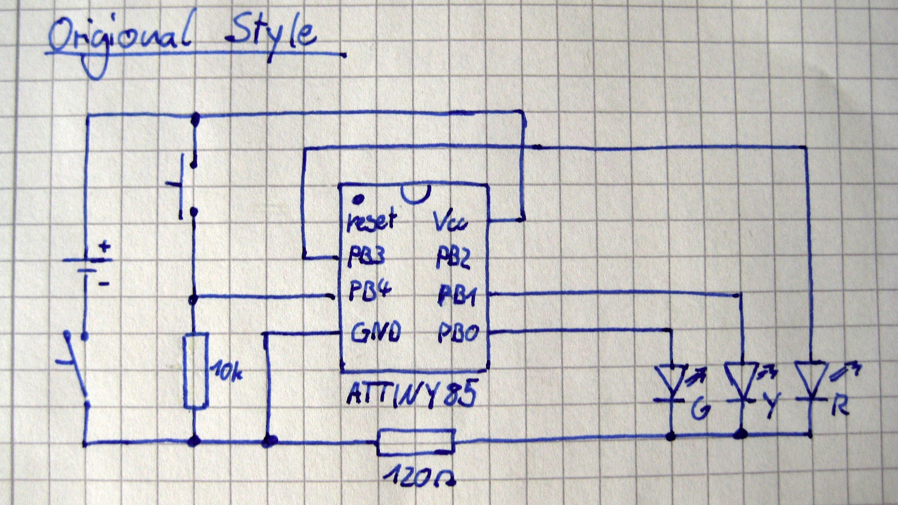
Yes, this is meant to be an instructable about software. However I stumbled across some small, but somewhat important changes.
All styles presented in the following are exchangeable, all work with the same code and do not behave fundamentally different. I've redrawn the original style by Victor8o5 to make it easier to compare.
Step 2: 'LAB' Style
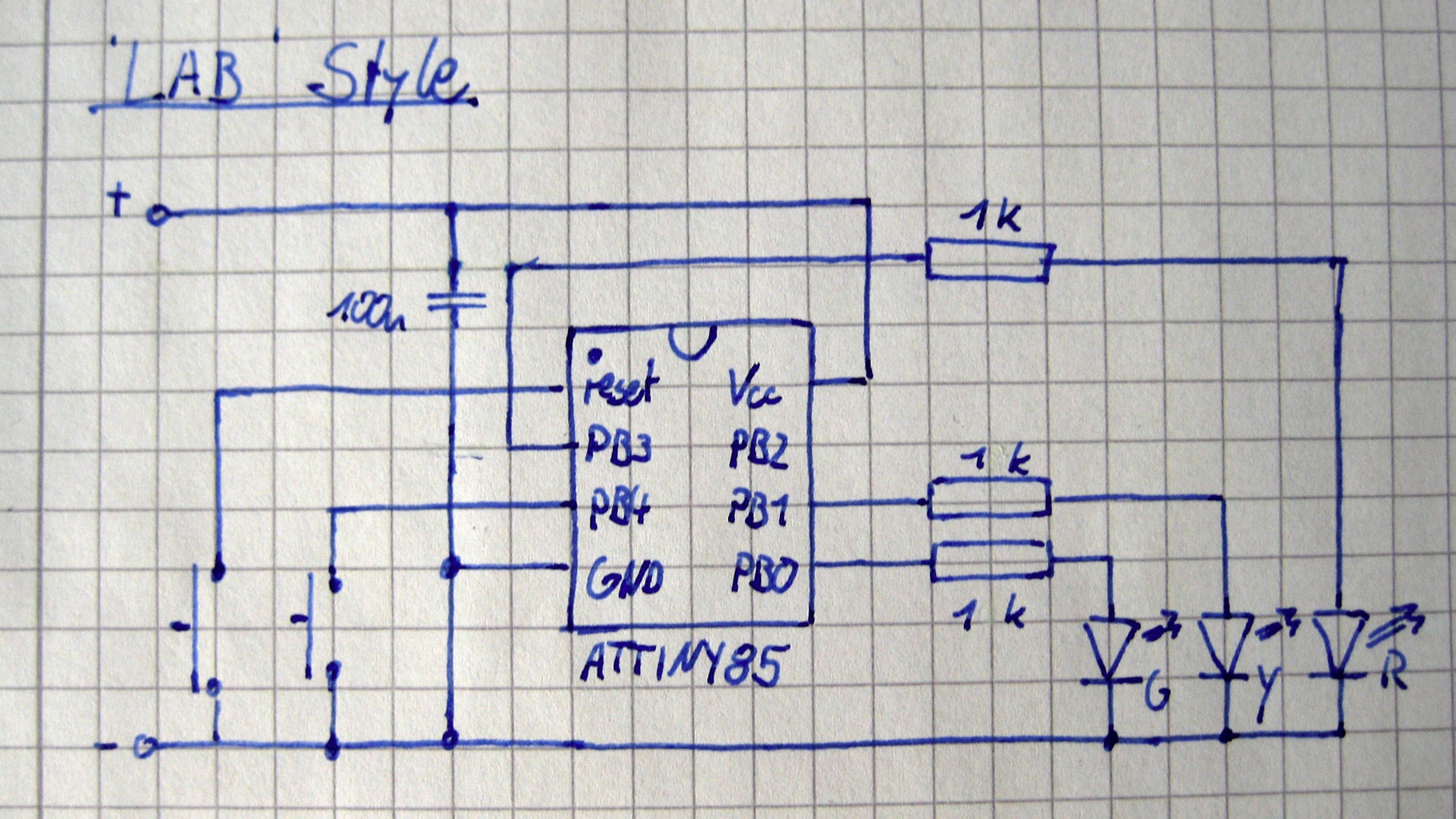
There were several changes required or at least helpful to program and debug the circuit in 'lab' conditions. The changes are:
- Replacing the battery with a regulated bench supply for convenience.
- Adding a small decoupling ceramic capacitor (100n): This provides increased environment noise immunity and is recommended for every application. However, if the circuit consumes very low currents, runs at "low" speed and has its power source right next to it it might be sufficient to leave it away, as in the original design.
- Adding a 1k resistor per LED and removing the 120ohm resistor: To program the Attiny85 in circuit it is required that all IO involved (in this case PB0, PB1, PB2) are 'isolated' with at least 1k. This prevents excessive current draw from the programming device.
- Removing the 10k resistor and moving the button to the low side: I wanted to use the build-in pull-up, because why use an additional part if you already paid for the function?
- Adding a dedicated reset button to perform a hardware reset without removing the power. It can be quite helpful for debugging.
Step 3: Optimised Style

If you want to build this circuit you properly want the solution with the least amount of parts and the lowest power consumption. I made the following changes to the original:
- Removing the on/off switch: In sleep mode this circuit consumes so ridiculous low amounts of current that a switch isn't required, the shelf-life of a CR2032 is still lower than the runtime.
- Adding an optional 100n ceramic capacitor. This is just a safety measure to smooth out short current pulses. I'm not sure how well CR2032 batteries can handle the on their own. Also, it's important that you use a ceramic capacitor, electrolytic or tantalum types have a significant leakage current which dominate in the 'deep sleep' mode. If you can choose get an X7R or X5R type ceramic.
- Increasing the resistor value from 120ohm to 220ohm: To archive the lowest possible active current I reduced the current flow through the LEDs. In my opinion the roughly 5mA make the LED bright enough, but you might want to tweak this value yourself. Usually you should use one resistor per LED , but in this case only one LED is switched on at a time, so it doesn't matter.
- Removing the 10k resistor and moving the button to the low side, just like in the 'LAB' Version.
Step 4: How to Use

This might me the most simple to uses device you've ever laid your hands on.
- To turn it on simply push the button.
- A random LED will light up.
- Repeat if wanted.
- Release the button.
- After two seconds the device turns off.
That's it.
Picture by Victor8o5 from this instructable under BY-NC-SA license
Step 5: 'True' Randomness

Many 'random' functions are in fact everything but random: they cycle through a list of arithmetic results based on previous results. This means if the start value is the same, the second, third and so on values will also be identical. To solve this issue the current time is often used as starting point, it's never the same.
Except you're coding for a microcontroller. They don't have an ongoing clock. If they are reset, they start from the default values. Sure, you could use the point of time of the button press as a source of random data, but to do that timers must be running, and thus the power consumption is relative high.
In my approach one LED is used as a source of random data. LEDs are sensitive to light and generate, if unpowered, a small voltage. The great thing is that this voltage is extremly sensitive to temperature changes, natural radioactivity, and other sources of noise. Those slight variations can be detected with the ADC of the Attiny, resulting in an almost random last bit. I say 'almost' because either the 1 or the 0 is slightly preferred, especially over short periods of time.
Even just this slight non-randomness is noticeable. Thus I only use 'random' noise as the seed (start value) of a 'random' math function. I've counted individual events (see list above). The result pretty much match the set probability of 40% red, 40% green and 20% yellow.
For even more randomness the value of the math function and new random noise values could be merged. I don't know how to do this properly, but if you do, please leave a suggestion in the comments.
Step 6: Pull-down Detection
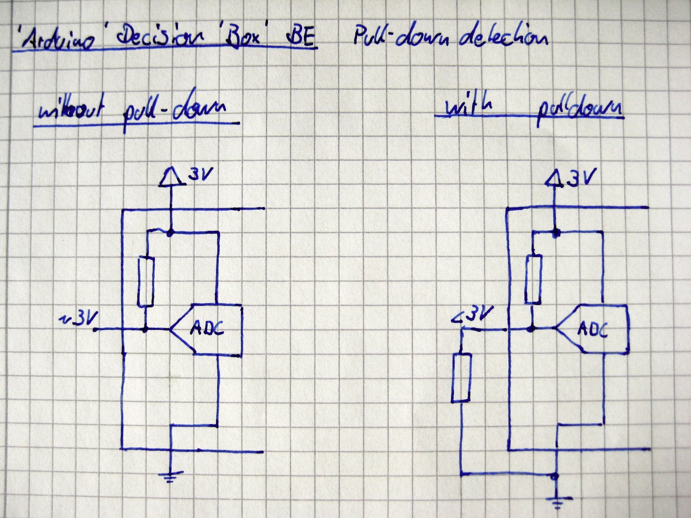
It seemed like I had only two choices, either the code would be compatible to the original project or the button wouldn't require a pull-down resistor.
The solution is simpler then I first thought:
If the internal pull-up is enabled and not external pull-down used the voltage at that input should be very close to the system voltage. If an external pull-down is used both resistors create a voltage divider and thus the voltage at that input should be significantly lower. All left to do was to get the ADC to read the value and compare it to the preprogrammed threshold. If the measured value is below an external pull-down is used so a so signal is active high.
Step 7: Pin Mapping
Instructables has always been about hacking and modifying.
If you should decide to use this as the base of your next project (you're free to do so!) it could be really hard to re-configure any IO, which is bad if you need a specific pin function, or want to archive the best layout possible.
That's is why I've added the file "pinout.h" to the project. In this file each LED and button is mapped to a IO of the Attiny. If you wish to move, say the red LED to PB2 just change the entries below //LED RED, //RANDOM 0 and //UNUSED IO. All values in the .c file will be automaticly replaced when compiling. Isn't that great?
In the same fashion you can also tweak the pull-down detection threshold and the percentage of the red and green LED (the yellow will be automaticly the remaining percentage) in the file user.h.
Step 8: Basic Flow Diagram

First off, it's incredible hard to squeeze an interrupt and sleep based program into a real flow diagram. I tried my best in the diagram above, I hope you still understand why the program is like it is. I recommend you to view this diagram side-by-side to the code to get a better understanding.
The goal is basicly to keep the microcontroller as long as possible in the 'deep sleep' mode called "power down". In this mode all clocks are halted and the processor can only be awoken with a "pin change interrupt" or "external interrupt". Well, all clocks except the watchdog, that's why it is used to generate timings.
In "ilde" mode the main core is halted reducing the power consumption by roughly two third (compared to a >99% reduction), but the huge advantage is that the microcontroller doesn't need any additional boot time (roughly 4 ms). Thus it is more practical to go into "ilde" if any interrupt is soon expected.
Let's have a view on the diagram:
- After the setup routine the device goes directly into sleep mode, where it stays until an interrupt occurs. In this case the processor wakes up and the interrupt handler will react on the event.
- Since the watchdog timer is not yet enabled and there was no previous button press the first interrupt starts the button debounce routine. This is done by starting the watchdog timer at an interrupt of 16ms. If any contact bounce occurs the pin change ('button pressed') interrupt will be fired again and reset the counter back to 0. In between each of those interrupts the processor has no work to do and thus will be send into "ilde" mode.
- Once the button reached a steady state (and doesn't bounce any more) the watchdog timer interrupt is enabled. Due to the steady state of the button the debounce routine can no be closed and the current state of the button used.
- If the button is pressed one LED will light up base on random data. Till the next interrupt it takes at least 100ms, so it's practical to send the device into "power-down" mode.
- If the button is then released the same debouce routine will be executed, but in the end the watchdog timer will be set to 2s for the LED time out. Again, the microcontroller has no work to do for the next two seconds so the "power-down" mode is chosen.
- Once the watchdog timer interrupt is triggered while not in debounce mode, it has to be the LED time out signal. Thus all LEDs are turned of, the watchdog is shunted down and the device is set into long-term "power-down" mode.
- It is possible that another pin change interrupt occurs while the watchdog is in it's 2-second LED time out period. In that case the current timer setting will be overwritten and the debounce mode entered.
Step 9: Sleep Timings
To estimate the power consumption of the Attiny we need to know when it is working. To do that I slightly change the code to always turn on the green LED on right after it woke up and turn it of right before it goes to sleep. Of course the pulses are way to fast to be noticeable with the bare eye so I hooked up my oscilloscope to get the data. To get more action within the field of view I changed the LED time out to 0.5 seconds.
Picture 1*:
The events (on-times) are so short you only see thin vertical lines. In order:
1. Button press
2. Corresponding watchdog time out
3. Button release (multiple lines due to bounce)
4. Corresponding watchdog time out
5. LED timeout
Lets zoom in on that a bit:
Picture 2:
Shows event 1-4. It took me only about 90ms to release the button.
Picture 3&4:
Shows event 1&2. Those are helpful to see how long the code actually takes to be processed. Keep an eye on the "Zoom level", in picture 1 it's only 5us per division while in picture 4 its 20us/div !
Picture 5:
Shows event 3&4.
Picture 6:
Shows event 3. The bounce is clearly visible now. The rather "wide" section in the middle of the right clutter is caused due to multiple interrupts within the same awake period.
Picture 7:
Shows event 5.
Not shown is the difference between the sleepmodes. In "power-down" nearly no power is consumed, while in "ilde" the consumed power is still 1/3 of the active mode. By the way the code works we know that the device is almost all time in "power-down", only right after a "pin change interrupt" it's in "ilde".
*I recomend to view the pictures in their original resolution.
Step 10: Power Savings
It's incredible hard to measure such high-speed current changes. A normal multimeter is waaay to slow, and my oscilloscope is only able to measure voltages. I already ordered a measurement adapter for my oscilloscope to do exactly that (the uCurrent Gold) but that this got somehow stuck in between shipping and customs. If I still feel like doing some measurements when I receive it I'll update this step, but I can't guarantee for anything. it never arrived. I got my money back, tough. Unfortunatly there won't be any real measurements
Till then you have to approximate the power consumption with the timings given before. I'll spare you the math but I calculated an effective runtime comparable to 10ms active mode. At the given 1Mhz and 3V the current consumption is roughly 0.5mA. With sleep modes the current consumption is 0.005mAs, a huge gain from 1.5mAs (3000 times less).
The current through a LED depends on the resistor and the voltage applied. With the original 120ohm resistor the LED draws 10mA, with my recommended value of 220ohm only 5.5mA. Sure the brightness will suffer, so you have to decide which solution you pick.
Assuming the CR2032 contains 235mAh you can get some more rolls out of the power saving version (assuming the LED is lit for 3 seconds each roll):
Original style + old code:
235mAh*60*60/(1.5mAs+10mA*3s)= 26857 rolls
Optimised style + new code:
235mAh*60*60/(0.005mAs+5.5mA*3s)= 51257 rolls
Also the standby time is greatly enhanced:
Original style + old code (active current = 0.5mA):
235mAh/0.5mA= 470h = 19,5 days
Optimised style + new code (power-down current = 0.2 uA):
235mAh/0.2uA= 1175000h = 48958 days = 134 YEARS
(a common CR2032 battery limits this to its shelf life of about 20 years)
Step 11: Final Words

I hope you enjoyed this read, if any questions are unanswered feel free to ask.
I'd like to thank Victor8o5 for sharing the original version with us, else I wouldn't have written this for sure. So if you haven't yet, make sure to check out his original version and version 2.0!
I don't know if you noticed this, but in the tags you'll find a unique 12 digit number. Google it to find everything related to this instructable. Feel free to add it if you think this is relevant to your project. ;)
This has been my first instructable for over three years (I started over with a new account) so any feedback is highly appreciated. You want to be notified when I publish new stuff? Subscribe. It's 100% free. :)
Happy coding
- nqtronix
PS: Dear instructables team, could you PLEASE STOP changing the output of the 'enter' key in the editor?! If I entered a new line, I want a new line, and not this "let us do the formatting for you" - rubbish. Same goes for other whitespace such as blank, tab od ALT+255. It's horrible annoying to 'hack' the stuff into the editor to make it work.
UPDATE: I created this (https://www.instructables.com/community/Option-for-no-auto-formatting/) forum post about this issue, if it annoys you as much as it does me, please state your opinion. It would help a lot. Thanks.
changelog:
2015.05.29
    1.5 updated information concerning real measurements & the uCurrent GOLD
2015.04.31
    1.4 added information about tagging
        fixed the date of version 1.3. "2015.03.19" seemed a bit off
2015.03.29
    1.3 added license information to embedded embedded (foreign) content
2015.03.18
    1.2 slightly optimised the layout with html editing
2015.03.17
    1.1 added everything which required a link
    1.0 release version
Picture by Victor8o5 from this instructable under BY-NC-SA license

Participated in the
Automation Contest

![Tim's Mechanical Spider Leg [LU9685-20CU]](https://content.instructables.com/FFB/5R4I/LVKZ6G6R/FFB5R4ILVKZ6G6R.png?auto=webp&crop=1.2%3A1&frame=1&width=306)


