

Introduction: LED Displays, Counters, Ad Signs


These are two older projects of mine, I found the design files in some older folders while looking for images for another instructable I was making. I will present two projects, showing the steps that need to be done by those who wish to make something similar.
I've only had two main LED projects during the years, one was a LED ad sign meant to bring attention to an arcade game bar, the other was a simple counter that had to be big enough to be seen from around 50 meters.
The projects were easy to build, the arcade game sign got place on perfboard, I haven't bothered to make PCB for every letter plus mainboard. Shaping the letters is at the choice of the builder, just take care to allow the same amount of current through each LED segment, to have the same brightness everywhere.
Let's move on to the first project, the arcade sign board!
Step 1: Building Letters Out of LED-s


Being the simplest thing of all we have to do, let's start with the mechanics part. Back then I didn't had the CNC mill, so cutting an enclosure for this project was a task to be done by hand.
I made a 5 x 7 hole matrix on a perfboard with 3 millimeter holes, to be my stencil when drilling the holes for the letter LED-s. I put that on the cable cover, and drilled out holes in a way to shape out the letters I needed. The text i needed to drill out was:
"JOCURI ELECTRONICE". I drew the letters on paper first, to make sure I get them right. Unfortunately I haven't made any pictures of the enclosure, so I can't show you building details.
For 5 mm LED-s you should drill 5.5 mm holes, otherwise, they're not going to fit in.
When you're all done with the enclosure, paint it, if you want, I sprayed mine with black spraypaint.
When the enclosure was done, I started to work on the letters. I pushed them down so they touched the board, and soldered them on bottom side. When you're done with that too, cut down the pins at the solder joint, and put away the pieces. Led pin excess wires are a good thing, don't throw them out, you can use them later as pad-to-pad jumper wires. We are using them to connect our LED-s in series, too.
To have the current consumption at a minimum, you'll have to think of connecting them in series. This way, the same 20mA flows through each one, lighting them all up. I had a power supply of 12 volts available, I decided to use that for this project. With a diode forward voltage of 2 volts, that gives me a maximum of 6 LED-s that can be tied in series.
Let's see some calculations for a few letters:
Letter J - 11 LED-s in total, I split them in a 5 and a 6 LED group. These LED-s have their forward voltage somewhere around 2 volts, so I didn't use current limiting resistor on that group. The 5 LED group instead has a total voltage drop of only 10V.
Let's see a resistor value for this group:
R = ( 12V - 10V) / 0.02mA = 100 ohms. This is even a common value to find in stores.
Letter O - can be split into 2 groups of 5 LED-s and a group of 6 LED-s.
Letter C - I split that into two 4 LED groups, and a 5 LED group. The resistor you need for a 4 LED group is:
R = ( 12V - 8V ) / 0.02 mA = 200 ohms
Letter U - can be split into 3 groups of 5 LED-s, you'll need to add a 100 ohm resistor at each group.
And so on, for all the letters you need.
Then, they must be connected to ground, and power supply. Since we must give a possibility to turn them off and on, we need to add a switching element. I added a bipolar transistor on the high-side. Please refer to the simple schematic from the photos to see how they have to be connected.
Step 2: Building the Control Unit

The control unit is a PIC16F873A, this is a very simple job for this capable little fellow, just some IO toggle tasks, and an eventual sweep speed setting. That is the whole algorithm. I think, the initialization routine, and the config bit setting is the only place where anyone could go wrong. Don't forget to select HS oscillator in the configuration bit section, if you choose to operate from a 20MHZ vrystal (or anything above 4 MHz), otherwise nothing will work, and you will end up waiting for microchip forum members to give you possible reasons why your processor isn't working as it supposed to.
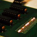
My controller board too was built on a perfboard, it has two LDO stabilizers, and the letter driver transistors on it. Aside of that, just wires, base resistors, and standard decoupling caps.
This is how my controller board looks like:
Step 3: Assembling the Ad Sign, Writing the Software

Now, that you have the enclosure and the letters ready, make the assembly. Push the letter LED-s through the holes you drilled, and glue them from the inside of the enclosure. I used a hot glue gun to do this.
I tested each letter before snapping it all together, I simply wanted to get over with the hardware part, to know I have something finished. I hooked up the pickit to ther PIC16F873A, and started to write the firmware for the PIC.
Because I wanted the PCB to be as simple as it could get, I had some complications with the software, the consecutive letters weren't even on the same port, I had to jiggle around with the port bits in the code.
Anyway, if you have a look on the code, you'll see which letter goes where, you can easily change it, too. This is the reason why I haven't given you a schematic. If you know which letter goes to which pin, making your own schematic shoudln't be that hard to figure out. If you're in trouble with this, just ask in the comment section.
I marked most of the code lines with the letters it has effect on, you can find the code attached to this step. The different blinking patterns are provided by the different functions you can see declared at the program beginning. The software runs through them consecutively.
Let's move on to the other similar project, the LED 24 second counter!

Step 4: The Segments, and Their Drivers


Because the guy who asked me to build this needed the digits as big as they could be, I built up every digit to look like an ordinary 7 segment LED display. Each segment consists of 12 LED-s, eliminating the need for current limiting.
This is an older project too, I don't have the eagle design files (yes, I used eagle before I got familiar with Altium) anymore, but i do have the PDF prints, which I am more than happy to provide.
The scaling is 1:1, the PCB-s were made with UV technique and gave me pretty good results.
I needed to keep the wire-count low, this was supposed to be commanded through wires. I had 10 wires going to each of the two displays:
- digit 1 BCD bit 0
- digit 1 BCD bit 1
- digit 1 BCD bit 2
- digit 1 BCD bit 3
- digit 2 BCD bit 0
- digit 2 BCD bit 1
- digit 2 BCD bit 2
- digit 2 BCD bit 3
- VCC
- GND
The 4511 IC was a good idea, instead of wiring 7 + 2 wires for each segment, and having trouble with the pin count, I ended up working rith 4 + 2 only. The 4511 is a BCD to 7 segment decoder, and is widely used by hobbyists even to these days. Where low pin count is a constraint, this IC is a good choice.
A good explanation on ow this IC works: http://www.sentex.ca/~mec1995/tutorial/7seg/7seg.html
I used something similar with the one controlled through transistors, but with two digits.
I recommend every beginner to build some of Mr. Tony Van Roons' circuits, they're very useful in practice, and you can really learn from them a lot.
Another choice could have been a MAX7219, I had two available at the time, those can drive up to 8 digits, and need only three wires to do so (SPI serial protocol). They're aren't as cheap as the 4511 IC-s were, though, so I kept them unused. If you take a look at my first instructable (control panel for workshop), you can see it working like a charm.
Here are some images of the PCB developing and etching process of the 4511 boards.

Step 5: The Processor Board, and the Assembly


The board is pretty much the same as with the other project, only this time the transistors aren't placed in the mainboard, but on the other end of the cable. A custom PCB was made for this main controller board, you can find the artwork for that PCB at the previous step, it's the one which's got 'vezerlo' in its name.
There are 3 pull-up resistors, which connect to each of the input buttons. So the program will be looking for a logic '0' on the input pins to detect a key-press.
The program for this is in many ways similar to the other firmware, a timer was added to keep track of milliseconds, seconds. But this time, you'll have to write the code yourself, based on the previous example.
An assembly rule of thumb: small components first, tallest last, IC-s need IC holder sockets!
Step 6: Final Words, Cleaning the Table
I'd like to thank you for reading this, and I wish you good luck with building it. I am always happy to answer questions, I hope to get just as active here, as I usually am on other forums.
Best of luck!

Participated in the
Microcontroller Contest


