

Introduction: Mini AT-99 Scorpion Gunship From Avatar


Hello everyone! I have a new one for you..... .... James Cameron's AT-99 Scorpion Gunship from the movie "Avatar"...
A twin-ducted fan VTOL craft, the Scorpion is a companion to the SA-2 Samson utility aircraft (hmmm.... maybe the next project?!?)... While the Scorpion's role was as an attack gunship, the Samson was mainly used as a transport for equipment, human(oids) and mobile labs...
The aircraft had obvious similarities to the AH-64 Apache Gunship with rocket pods, hellfire missiles and gun pods. Modelling the ducted-fan, landing gear and weapons were the main challenges for this project.
Step 1: Materials and Tools


For this project, I was proud to use a new acquisition - a Dremel 3000. Unlike the mini mite, there was no need to wait for a 6-hour recharge before you can use the tool. But of course, nothing beats the mini mite for really low speed detailing jobs.
Listed below were the tools used for this project:
-
Dremel 3000 and Dremel minimite with the following attachments/bits:
- Drum sander (course & medium grade)
- Disc Sander (fine grade)
- Reinforced cutting wheel
- Grinding Stone (assorted drum and cone-shaped)
- Olfa Handsaver art knife (with standard blades)
- Elmers multi-purpose white glue
- handy clamps
- fine tweezers
- ruler and mechanical pencil
- vinyl cutting mat
Step 2: Schematics


There were no posts from blueprints.com for this particular craft although I found an image from the avatar-forums group. The url for the schematics is http://www.avatar-forums.com/avatar-gallery/showfull.php?photo=234.
Some enhancements were made to the original image for it to be usable in this project. I used Picasa image editor and adjusted the light fill and highlight preferences to bring out the lines in the drawing.
I also used images from the following sites as references:
http://james-camerons-avatar.wikia.com/wiki/Scorpion_Gunship
http://www.warbird-photos.com/gpxd/viewtopic.php?f=9&t=22834
I wish to acknowledge all contributors of the images and drawings for making this build possible!!!
Step 3: Fuselage


I started with the single biggest piece of the build - the fuselage. Rule of thumb was to identify major sub-assemblies and gradually build up the much smaller parts into it. Major sub-assemblies all come together in the final step of the build.
For the fuselage, large popsicle sticks (almost the size of tongue depressors) were used. An initial sketch was done based on the schematics and carved into shape. Five pieces were needed for the width of the aircraft.
The side avionics bay were fabricated from laminated scrap wooden ice cream cup spoons and carved using the schematics and images as references. These were glued to the main fuselage, clamped and set to dry.
Step 4: Ducted Fan and Rotor Assembly


One of the more interesting step in this project was the fabrication of the ducted fan assembly. The circular duct (or ring) that housed the twin rotors was specially fun to build. I used two ice cream cup wooden spoons sandwiched at 90 degrees of each other. Wood has the tendency to split along the grains and the spoons laminated at 90 degrees strengthens the circular duct.
A pilot hole was drilled at the center of the laminated piece. The pilot hole was gradually increased using varying sizes of grinding stones and drum sander attachments. The finished circular duct should resemble a wooden 'engagement ring'.
For the individual blades of the rotor, thin coffee stirrers were split into thin strips, shaped with a sanding disc attachment and cut using the circular duct as a guide (for the blade length). I experimented with three and four bladed versions (although the instructable only shows steps for the three-bladed version). A bit of toothpick made up the hub that binds all three blades of the rotor.
Spare popsicle sticks were used for the rotor mount inside the circular duct assembly. The rotor mount was glued inside the duct with space for the top and bottom rotors.
The left and right mounts for the ducted fans were from the spares left from the fuselage build. The shape was patterned after the schematics in step 2.
The rotor shaft housings were carved from thin coffee stirrers. These were glued on top of the left and right mounts of the ducted fans.
After the glue has dried, slots were carved into the ducted fan mounts. The slots hold the round pivot rods that connects the ducted fan mount assembly to the air intake/exhaust assembly (fabricated in the succeeding step). When connected to the air intake/exhaust assembly, the rods enable the tilting of the left and right ducted fan assembly at varying angles. The rods themselves were made from round toothpicks cut to size. These were glued to the slots on the ducted fan mounts.
The circular ducted fan assembly was then glued to the fan mounts. Scrap regular popsicle sticks were used to prop up the ducted fan assemblies to ensure an even bond with the fan mount.
As the ducted fan assembly dries, triangular bits of thin coffee stirrers were sliced to form the tree cutting tool. These were mounted on the leading edge of the completed ducted fan assembly. The tree cutters were later 'sharpened' using a disc sander attachment on a mini mite.
Step 5: Air Intake/Exhaust


The air intake/exhaust connects the ducted fan assemblies to the fuselage. It was cut from a regular sized popsicle stick and carved into shape using the illustrations and images as reference. Thinner coffee stirrers were cut and shaped for the engine exhaust. These were mounted on top of the air intake/exhaust. Holes were drilled at an angle to ensure a perfect fit for the pivot rods of the ducted fan assemblies.
The completed ducted fan and air intake/exhaust was then used as a guide to carve a grove on top of the fuselage. The ducted fan assemblies mounted on the air intake/exhaust should be movable at an angle depending on the builders preferences.
Step 6: Tail and Rudder Assembly


The tail and rudder assembly were from spares leftover from the fuselage build. The horizontal stabilizer was cut and shaped using a disc and drum attachment using the schematics and images as references.
After shaping the rudders, it was cut in half, glued at an angle and set to dry. The finished rudders were glued at both ends of the horizontal stabilizer.
A slot was made for the tail and rudder assembly at the trailing end of the fuselage using a drum attachment. It should fit the finished tail and rudder assembly for installation at the final step of the build.
Step 7: Landing Gear Assembly


The most delicate part of the build was fabricating the landing gear assembly. The individual parts were tiny and brittle.
The bend on the ski ends were from a carved toothpick. A thinner toothpick was used for the main 'ski'.
The legs that connect the 'skis' to the fuselage were carved from two types of materials, thin coffee stirrers and wooden ice cream spoons. Illustrations show differences in thickness for the front and back 'legs', hence different materials were used. A pilot hole was drilled and very carefully carved to retain a thin 'leg'. These were glued to the fuselage at points shown in the schematics from step 2. The 'skis' were added to complete the landing gear assembly.
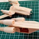
Step 8: Rear and Front Wing Weapons Bay


For the rear and front wings housing the various weapons of the Scorpion Gunship, regular popsicle sticks were carved to form a thin, wing-shaped piece using a disc attachment and cut into the size specified in the schematics. The wing tips were cut, glued with a slight bend and set to dry.
The various weapon loads were from the 'scraps' box.... Toothpicks for the hellfires and minigun barrels, and hexagon-shaped spare coffee stirrers for the rocket pods. The minigun receivers and hellfire mount(s) were also from spare, thinly sliced coffee stirrers.
First, the rear wing weapons bay were glued to the fuselage. Then, the five(5) rocket pods (per wing) were installed. Finally, the hellfire assembly was glued at the rear wing tip.
The front wings were glued at the leading edge of the fuselage just below the pilot's cockpit. The mini gun were glued at the wingtips and the mini gun receivers below the front wings. The underwing mini gun barrels were added to the ends of the mini gun receivers.
Step 9: And Finally....


A thin coffee stirrer was carved for the tail support. The tail support locked the tail assembly in place.
The targeting module that was mounted in front of the fuselage was fabricated from laminated scrap coffee stirrers. Another thin scrap was used as the bracket connecting the targeting module to the fuselage.
After the tail assembly and targeting module, the combined ducted fan and air intake/exhaust assembly was finally glued on top of the fuselage. This should fit snugly if the assembly was test fitted as shown in step 5. The completed AT-99 Scorpion Gunship is now ready to take on the Na'vi.
Mr. Cameron, your squadron awaits!


