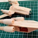
Introduction: Mini AT-ST Popsicle Stick Model
Hello everyone! Another project from the Star Wars Universe - A mini All Terrain Scout Transport (AT-ST) popsicle stick model...
The "chicken walkers" were more of a challenge to build compared with other fictional crafts since the mini AT-ST has to balance on two really skinny mechanical legs. That said, together with the very slow curing time of white glue combines for a rather difficult project.
Step 1: Tools & Materials
Below is a list of tools used in this project:
- Dremel minimite with the following attachments/bits:
- Drum sander (course & medium grade)
- Disc Sander (fine grade)
- Reinforced cutting wheel
- Grinding Stone (small, drum-shaped)
- Olfa Handsaver art knife (with standard blade/s)
- Elmers multi-purpose white glue
- handy clamps
- fine tweezers
- ruler and mechanical pencil
- vinyl cutting mat
Materials used were varying sizes and types of popsicle sticks, wooden coffee stirrers and toothpicks. The colored 'tongue depressor-sized' popsicle sticks were used in the final assembly to prop up the engine drive assembly at the same level with the mechanical walkers' legs. A piece of bamboo chopstick was used for the gyro system connecting the main turret with the engine drive assembly. Also useful were bits and pieces from my 'spares' box for tiny parts like the simulated mini blaster and concussion grenade launcher mounted on the both sides of the main turret. The 'spares' were leftovers from other popsicle stick projects.
Step 2: Schematics
Schematics for the AT-ST was from the site The-Bluprints.com. It hosts some of the largest collection of free schematics and this project was definitely not possible without them....(thanks guys!!)...
For anyone who would rather go straight to the schematics, the image URL is : http://www.the-blueprints.com/blueprints-depot/sciencefiction/star-wars-imperial/at-st2.GIF
The image was reduced to 80% of the default GIF image and printed on paper to serve as blueprint for the build. The reduced size of the main turret should match the size of a regular popsicle stick.
Step 3: Main Turret
For the main turret, I cut six (6) pieces from regular sized popsicle sticks to match the size of the illustration in the blueprint. After the glue has set, I used a drum and disc sander attachment to grind and shape the turret based on the schematics.
The front armor housing the main blaster and command viewports were separately glued and sanded into shape. The slot for the main blaster was carved using a reinforced cutting wheel from Dremel.
Tiny parts for the command viewports, ingress/egress hatch, mini laser blaster and concussion grenade (and their mountings) were cut from various parts from the 'spares' box and sanded to its final shape using a fine disc sander attachment.
Step 4: Footpad and Leg Assembly
The two (2) footpads of the walker were cut and carved into shape from wooden starbucks 'stirrers' using a fine disc and drum sander attachment.
The simulated fence cutting blade was carved from a toothpick, sliced in two and glued to the two (2) dome-shaped footpads. The length of the fence cutting blades were intentionally lengthened to act as a 'foot' extension. The extended length increases the footprint of the walker and acts to counter balance the weight of the main turret when mounted in the final assembly. Equal sized toothpicks were cut and glued to the footpad assembly.
For the AT-ST's legs, wooden starbucks stirrers were slotted using a reinforced cutting wheel. The slots should fit the toothpicks in the previous footpad assembly.
For the AT-ST's 'thighs', regular popsicle sticks were used, carved and shaped according to the size and specs in the schematics. Barbecue sticks from the 'spares' box were cut to form the main joints. Spares were again used for the joint covers of the AT-ST 'thighs'.
The legs and thighs were then glued based on the bluprint and allowed to dry overnight. The footpad assemblies were then inserted into the walker's legs and glued in place. The completed sub assemblies must now be able to stand on its own..
Step 5: Main Blaster Cannon
The main blaster cannons were the tiniest parts in the build and required a very delicate sanding 'touch'. A toothpick was initially sanded to a small cylinder-shape to represent the barrels and tapered towards both ends.
Spares were used for the gun mounts and a piece of barbecue stick for the blaster counter weight.
Step 6: Drive Engine & Gyro System Assembly
For the walker's drive engine, a two-layer 'sandwiched' wooden stirrer was used. The flat octagonal shape of the drive engine was carved using a fine drum sander attachment. Side slots for the drive shafts were cut using an olfa cutter.
A bamboo chopstick was tapered using a drum sander and cut to the desired length based on the gyro system illustrated in the blueprint. I highly recommend cutting the bamboo chopstick a little longer since it'll be easier to shorten it in the later stages when mounting the main turret. With the lengthened gyro system, you'll have the option to position the main turret facing up, down, left or right. The bamboo stick gyro system was then glued on top of the drive engine and set aside to dry.
Two (2) drive shafts were fabricated from scraps and mounted in the slots cut in the sides of the drive engine assembly. After these were allowed to dry, a drum sander was used to shape the end of the drive units parallel to the drive engine assembly. This increases the contact area where the drive shafts meets the leg assemblies.
Step 7: Put It All Together....
For the final assembly, I fabricated a temporary jig using colored 'tongue depressor-sized' popsicle sticks and oddly shaped 'scraps' to prop up the engine sub assembly with the same level as the walker's mechanical legs. The legs should line up with the engine drive shaft from the previous step.
While waiting for the engine and leg sub assemblies to dry, the blaster cannon assembly was glued to the blaster cannon 'slot' in the main turret. You have the option to mount the cannon pointing upwards (to blast Ewoks in gliders!) or downwards.
Finally, the completed main turret assembly was glued to the desired position on the engine/gyro system sub assembly.
Fabricate a squad of walkers and go after those pesky Ewoks!!!

Finalist in the
Pocket Sized Contest

Participated in the
Instructables Design Competition

Participated in the
Holiday Gifts Contest


