

Introduction: Mini Gunstar Popsicle Stick Model


**** Greetings Starfighter! You've been recruited by the Star League to defend the Frontier against Xur and the Kodan armada.... ******
Straight from the 1984 movie 'The Last Starfighter' here's a project to create the Gunstar, a heavy fighter that single handedly took out an entire fleet of Kodan Deck Fighters and their command ship.
The popsicle stick model itself was literally "heavy" since it required nine (9) laminated pieces of tongue depressor-sized popsicle sticks for the fuselage, four (4) pieces of regular popsicle sticks for each engine assembly (the model has a total of four engines!), and sixteen (16) pieces of tongue depressor-sized popsicle sticks to complete each wing (the model has two wings!). This made the finished model weigh a lot more than previous popsicle stick mini models.
I estimated the complexity of the project to be 8 out of 10 due to the heavy grinding, sanding and shaping done to complete the model. Overall, this was a very interesting build. The finished model came out pretty good specially with the "death blossom" weaponry deployed.
Step 1: Materials and Tools


Tools used for this project were:
- Dremel Rotary Tool Model 3000 and MiniMite with the following attachments:
- 1/2 and 1/4 inch drum sander (fine & coarse grade)
- fine and coarse sanding disc
- #125 and #193 high speed cutter
- Olfa cutter with #11 Xacto Blade
- Fine tweezers
- mechanical pencil and ruler
- various mini clamps
- Elmer's white multi purpose glue
- vinyl cutting mat
Step 2: Schematics and Images


Thanks to the internet, memories of movies shown decades ago are immortalized in shared pictures, web logs and various online documentations and articles. Schematics was from the ever-reliable blueprints.com web site. The URL for the schematics is
http://www.the-blueprints.com/blueprints/sciencefiction/science-fiction-misc/35305/view/gunstar_last_starfighter/
Pictures from various websites provided the various perspectives that aided in modeling the Gunstar. Keywords used to find images via bing and google were "Last Starfighter Gunstar". URL for images in this instructable are:
http://www.meshweaver.com/portfolio/side.jpg
http://www.igorstshirts.com/blog/conceptships/gunstar_concept_ship.jpg
http://www.meshweaver.com/portfolio/perspective_.jpg
http://www.meshweaver.com/portfolio/attack_vector.jpg
Images from the site meshweaver.com were stunning and provided a lot of details. This project will never become a 3-d creation without the images from exciting websites. Again, my heart filled appreciation to people who unselfishly provide amazing images of spaceships and aircrafts!!
Step 3: The Fuselage


Nine (9) layers of tongue depressor-sized popsicle sticks were laminated for the fuselage. The shape of each layer was patterned after the side-view schematics from Step 2.
After drawing guidelines in the laminated fuselage using the illustrations and schematics as patterns, carving and shaping were done using the following Dremel attachments:
- 1/2" coarse drum attachment for rough sanding the general shape of the fuselage
- 1/4" coarse/fine drum attachment for detailing the navigator and gunner's cockpits
- Coarse/fine disc attachment for smoothing and finishing the fuselage
A fine disk attachment was used to make the circle rear access door from a thin wooden coffee stirrer. The rear access door was glued to the flat, rear end of the fuselage.
The same attachment mounted on a Dremel was used to shape the underside gun turret housing. The underside gun turret housing was glued below the navigator's cockpit.
For the five (5) gun turrets, I laminated one (1) thin and one (1) thick wooden coffee stirrers and shaped it into a cylinder using a fine drum sander attachment. I carefully shaped the end into a dome and cut it to size, repeating this step to make five (5) gun turrets.
One of the gun turrets was glued underneath the gunner's cockpit, just in front of the underside gun turret housing. Two (2) turrets were glued to both sides of the fuselage, just behind the navigator's cockpit.
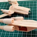
Step 4: The Engines


Four (4) regular popsicle sticks cut to size were used for each of the four (4) massive engines of the Gunstar.
Each laminated set was sanded into shape using a coarse/fine 1/4" drum attachment. This step was repeated four (4) times to make the four (4) engines.
A pilot hole was drilled at the rear end of each of the engine for the engine exhaust. I used a #125 high speed cutter attachment for the pilot hole. With the pilot hole as guide, a #193 high speed cutter attachment in a MiniMite moto tool was used to finish the exhaust nozzle. Finally, a hole was carefully drilled at the front end of each engine using a #125 high speed cutter attachment to model the front directional thruster.
Twelve (12) tiny wooden circles were carefully sliced off the end of a round toothpick for each of the engine's three (3) lateral directional thrusters. Each set of three (3) lateral directional thrusters were glued at the top and sides of each engine assembly. A suggestion for precisely setting each individual thruster in place on the engine: I used the tip of the olfa cutter to pick up and place each individual thruster instead of using a tweezer.
Step 5: The Wings


Two (2) pieces of wing leading edges were cut from wooden ice cream cup spoons. The two pieces were used as pattern to guide sanding and shaping the Gunstar's massive wings. These 'patterns' would ultimately be joined to the leading edges of the wings to make up the the "Death Blossom" weapons array.
A total of sixteen (16) layers of tongue depressor-sized popsicle sticks were needed to make each wing/weapons bay (Death Blossom) of the Gunstar. A lot of sanding and shaping was required to model the Gunstar's two (2) massive wings/weapons bay (Death Blossom) assemblies.
For the wing itself, twelve (12) layers of tongue depressor-sized popsicle sticks were initially cut, glued and sanded into a cube shaped solid block. This step was repeated to make the other wing.
Another two (2) layers were glued to each side of the a finished block to account for the shape of the huge wing based on the wing 'pattern'. You should now have a 'T' shaped solid block of wood.
Then came the heavy sanding and shaping of the finished 'T'-shaped blocks. The wing pattern was initially drawn on both ends of the solid block. A 1/2" drum sander attachment with a coarse grit was used to carve the solid block using the pencil pattern drawn as guide.
To get the top-to-bottom shape of the wing, a guide line was drawn based on the Step 2 top-view schematics. Heavy grinding, sanding and finishing using a 1/2" drum sander attachment with coarse/fine grit were needed to carve the top-to-bottom shape of the wings.
After the correct shape has been achieved, slots were carved at the wing leading edge patterns to model the "Death Blossom" weapons bays. The slotted wing patterns were glued to the front end of the wings. Spare popsicle sticks were made to frame the "Death Blossom" weapons array.
Pieces of beveled thick wooden coffee stirrers were used for the wing trailing edge gun turret mounts. After the adhesive joining the trailing edge gun turret mounts to the rear end of the wing has dried, the gun mounts were shaped using a fine disc attachment in a MiniMite moto tool. Finally the Gun turrets (from Step 3) were glued to the wing trailing edge gun turret mounts.
Step 6: Putting It All Together


With the major components completed, putting it all together was truly rewarding. There's great satisfaction witnessing the Gunstar taking shape and having the details added gradually.
The wings were glued, one at a time, to each side of the fuselage. Stacked spare popsicle sticks were used to prop up the fuselage while the glue binding the wings to the fuselage dries.
A thin strip of spare popsicle stick was cut to size that should fit the width of the slots in the "Death Blossom" weapons array bay. Really tiny holes spaced evenly apart were drilled using a #125 cutting tool attachment to simulate the "Death Blossom" weapons array. The strips were cut in lengths that should fit inside the four (4) weapons bay slots in the wings. Each strip was glued into each slot and allowed to dry. Again, the tip of an olfa cutter (instead of a tweezer) was used to pick up and set each "Death Blossom" weapons array in the wing slot.
Four (4) landing gear booms were made using a round toothpick, cut and shaped using the Part 2 top-view schematics and images as guides. These were glued at the junctions where the wings join the fuselage.
The four (4) engine mounts were from a thick wooden coffee stirrer, beveled at the four ends using a fine disc sander attachment. Each of the engine mounts were glued at the top and bottom ends of the wings near the edges. After the engine mounts have set, a 1/4" drum sander attachment with a fine grit was used to shape a curve in the inner edges to accomodate the cylindrical shape of the Gunstar engines.
Spare wooden ice cream cup spoons from Step 5 were used to make the four (4) landing gear assemblies of the Gunstar. These were glued at the rear end of the landing gear boom and just on top of the wing assemblies.
Probably the trickiest part of the build - gluing the engines to the engine mounts...
I began with marking the spot where the engine mount joins the engine using the side-view schematics and images from Part 2 as guide. I placed white glue on both the engine and the engine mount and allowed both to dry separately . This process pre-coats the surface of the two parts and allows for a quick bind after a final coat of glue has been added and both parts joined. The method was repeated until the four engines were set and aligned properly.
For the "Death Blossom" covers that open to reveal the weapons array, a strip of thin wooden coffee stirrer was used. Each cover was cut and shaped using an olfa cutter, beveled at the end with a fine disc sander attachment and glued near the edge of each weapons bay at the front wing tips. This was done for each of the four "Death Blossom" weapons array.
Finally, a thin toothpick was made thinner using a fine disc attachment in a MiniMite moto tool and cut into four (4) tiny pieces for the "Death Blossom's" cover hinges. These were glued at the junction of the covers and the wing edges and were meant to strengthen the bond between the "Death Blossom" covers and the wings.
Congratulations! You've just created the last of the starfighter... errr... Gunstar!
And until a sequel is produced..... For Rylos! Victory or death!!!

Participated in the
Epilog Challenge V

Participated in the
Instructables Green Design Contest


