

Introduction: Mini Star Trek Galileo Shuttlecraft Popsicle Stick Model


Hello everyone! Here's an instructable that can be built in a day - A Galileo shuttlecraft from the original Star Trek series.
A new concept when the Sci-Fi series was launched in the '60s, shuttlecrafts were designed to provide short range transport for explorers and equipment when the USS Enterprise's transporter system proved ineffective or impractical.
This mini popsicle stick project depicts the shuttle in two modes, in flight and landing modes.
Like all popsicle stick projects, the time-consuming element was the lengthy drying time of Elmer's white glue. All wood parts were patterned straight from a couple of available schematics from the internet.
Probably the simplest project that can be done in a day (even by a novice builder), the entire instructable consisted of only one (1) fabrication step. Only twenty-one (21) pictures were needed to provide an illustrated step-by-step guide in building the shuttlecraft.
This projects is dedicated to Leonard Nimoy, the american actor who played Mr. Spock in the original series. LLAP!
Step 1: Materials and Tools


Only 10 layers of wooden ice cream cup spoons make up the main fuselage of the shuttle. The other parts came from my spares box and small wooden dowels (for the left and right booster propulsion).
Tools used for the build were as follows:
- Dremel 3000 & Dremel Minimite with the following attachments:
- Coarse and Fine Drum sander
- Fine disc Sander
- Standard cut-off wheel
- Olfa cutter
- Fine tweezers
- Mechanical pencil
- Ruler
- Various Clamps
- Elmers White Glue
- Cutting mat
- Dremel's workstation and flex tool shaft proved invaluable for this build
Step 2: Schematics and Images


The keywords I used for both Bing and google images search for pictures and schematics were "star trek galileo shuttlecraft".
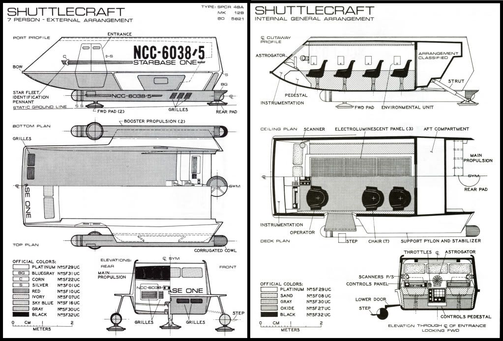
The main schematics I used were from ex-astris-scientia.org & photobucket. The two sites provided the only usable blueprints available (so far!) depicting the shuttle in both landing and flight mode.
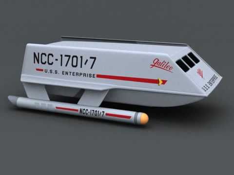
Other images provided detailed reference for the shuttlecraft's other details such as the landing gear assemblies and aft main booster.
I'd like to acknowledge the generous providers who posted the following useful reference for the project:
http://www.ex-astris-scientia.org/scans/galileo.jp...
http://i294.photobucket.com/albums/mm106/Linnear17...
http://s92.photobucket.com/user/Finktim/media/Star...
http://i.ytimg.com/vi/SVe5u8z0yf8/hqdefault.jpg
Similar to my two previous posts, I'm including the plans I used for the build (in .pdf) ...
Attachments

Step 3: Main Fuselage and Fabricating/assembling the Other Tiny Parts


The main fuselage consisted of ten (10) layers of shaped wooden ice cream cup spoons with eight (8) layers comprising the much smaller crew compartment. Fortunately, the schematics clearly show the demarcation between the inner and outer layers.
As I mentioned before, the eight (8) inner layers and the two (2) outer layers for the Main fuselage were patterned directly from the schematics from ex-astris-scientia.org. The two (2) outer layers were added to each side after the eight (8) inner layers were finished with a coarse/fine drum sander and fine disk sander attachment on a moto tool.
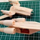
The booster propulsion consisted of two (2) small wooden dowels with the ends shaped with a fine disk atatchment on a moto tool.
The wing stabilizers and front/rear booster propulsion mounts were from my popsicle sticks spare box, cut into shape with an Olfa Cutter.
The wing stabilizers, front/rear booster propulsion mounts and the cylindrical booster propulsions were glued at the rear midline of the main fuselage using the images and schematics as reference guides.
A midline marker was fabricated from a toothpick and glued at the left and right front sides of the main fuselage. This completes the shuttlecraft in flight mode.
To make a shuttlecraft in landing mode, an additional four parts need to be made - The three (3) landing pad disks and the rear landing strut.
For the three (3) landing pads, tiny disks were shaped and cut from the end of a small wooden dowel using a standard cutting wheel attachment on a moto tool.
The rear landing pad strut was made from a toothpick shaped using a fine disk sander attachment. One (1) of the landing pads was glued to the end of the strut using the schematics as reference guides. Two (2) pads were glued at the leading edge of the left and right booster propulsions.
This completes the shuttlecraft in landing mode. A piece of cake!


