

Introduction: 0.1 Sec Accurate RTC GPS Wall Clock - Arduino 96x8 LED Matrix


This is an over-designed clock, but the basics are re-usable. The difference with almost all other GPS clock projects is the real accurate time, and not the usual 1-2 second error when only using the NMEA output.
Time accuracy.
Accuracy is relative, but for a clock more than ±0.1 second is visible for the human eye. That is, if you watch the flip of the second compared to another NTP or radio-controlled clock. You need to know the long-term precision, specified as the drift. In the DS3231 RTC series you can get a lot of different chip versions: The DS3231SN is temperature compensated, with about 1 sec/week at room temperatures and 2 sec/week at extremer temperatures. The DS3231M version has about 3 sec/week drift, but is better shock resistant. For one year this adds up to about 3 minutes. If we want to keep the time within ±0.1 second precise and consider the process time, we must sync our RTC at least every 4 hours.
NTP time is useful, but you need a network connection. For a small stand-alone project GPS/GNSS is a good option. Both solutions are using atomic clocks as a timesource. Internally a GNSS chip is accurate to nano-seconds, with an error of about 30 cm/nano-second. Even if your FIX has a location error of 1000m, the time is still within one micro-second accurate. Every time your GNSS chip has a FIX, it will sync the internal RTC. With simple consumer chips you can sync the external RTC DS3231 within milli-second accuracy, if you use the PPS PIN. If you have good GPS reception throughout the day, the accuracy of the clock is close to 5 milli-seconds.
The RTC inside the GPS chips has very bad long-term accuracy, therefore we must ensure that the GPS had a FIX in de last minutes before it is good enough to sync the DS3231. The GPS chip only needs the time to estimate which satellites are overhead, for that even the exact minute is not important.
Most people don't care about the seconds, or even the exact minute. But if you automate things, it is good to have your own little 'time controller'. The start of the minute, and thus the flip of seconds, are timezone independent.
Supplies
Arduino Nano v3 [just the common 5 volt version], not the Every or 3.3 volt versions]
GPS board with PPS PIN [Ublox NEO M8N or compatible] [Amazon]
DS3231 board [all chip versions are fine]
Breadboard + jumper wires + USB cable
optional: LED matrix FC-16 + power supply [Amazon]
optional: LEDs + resistors
optional: external GPS active antenna [Amazon]
optional: custom designed PCB, for wall clock at the office
optional: custom casing & mounting system
Total cost
Depending on how fancy you make it, material for the project is EUR 100,- to 200,-. If you are on a budget, you can make one with tiny display for EUR 35,-.
Step 1: GPS Location FIX

First hardware
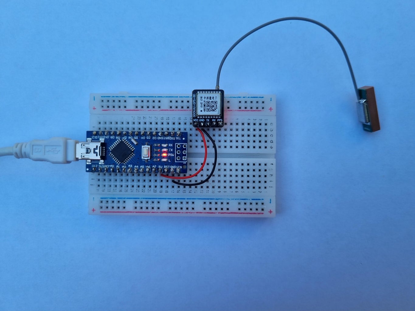
The first thing we check: does the GPS get a location FIX ? Just put the Nano and the GPS in your breadboard and wire the GND and VCC PIN. The Nano 5V PIN has 2 functions:
- From USB you can power low current devices
- If you have an external 5V powersource you can power the Nano. My advice is never to use the VIN PIN, the on-board power regulator sucks.
No code here, we just use the Nano as a powersource for the GPS. Connect the Nano to USB [PC, laptop, phone charger, powerbank, etc.] Both power LEDs should turn on, and we wait for the GPS to blink. On the photo above you see a small GPS board, used in drones and other mobile devices. It works fine outdoors, but for indoor usage it's not good enough.
GPS antenna.
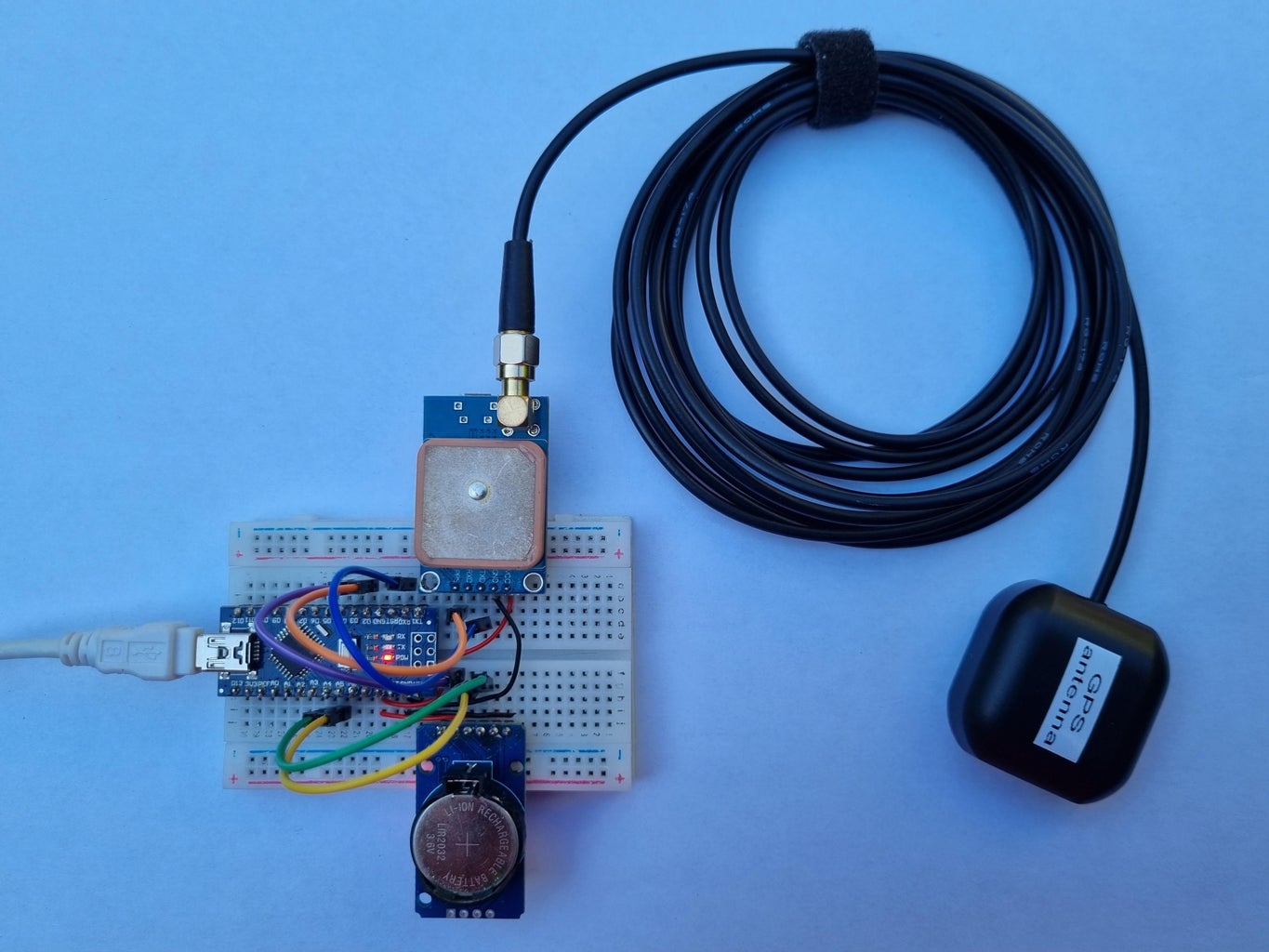
The downside of GPS/GNSS is the indoor reception, and the ability for the chip to get a FIX. Getting the indoor FIX is easier with every new chip generation, and with a good active antenna. If you are outdoors, or in a building without concrete/metal in the roof, you should get a first FIX within 30sec. Indoors this may take 2 hours, or even no FIX at all. If you get no time-sync, there are some tips:
- Get an active antenna [with SMA connector], a cheap car antenna with 3 meter cable and L1-band is fine.
- Avoid wiring and steel above the antenna, in your project and in/outside the building.
- Keep the antenna away from electric and/or electronic devices. Sometimes you need at least 5 meter of clearance! Turn off your TV, PC, microwave, power tools, battery charger, and everything else nearby.
- Avoid concrete above the antenna.
- Avoid varnished wood above the antenna.
- Move closer to a window, or a few meters higher.
- If nothing helps, power the GNSS chip outside with a clear view of the sky and let it charge the backup battery for 1 hour before you move it indoors.
- bad weather can cause the lost of signal indoors for many hours
The NEO-M8N in the photo below is actually a multi GNSS chip, which uses GPS, Glonass, Galileo, etc. We use it with its default factory settings in the whole project. Any GPS board will do, as long as you have 5 PINs: VCC, GND, Tx, Rx and PPS.
Step 2: GPS + RTC
Additional hardware
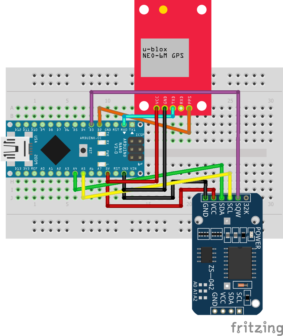
Add the RTC to the breadboard, this must be a DS3231 chip. You need one with 6 PINs, because we configure and use the SQW PIN as 1Hz. In the picture and the drawing, I used the same color for the wires. Notice that I bend the 90° PINs straight and that the GPS and RTC are flat on the breadboard, you don't need to.
Compleet the GPS wires:
- Connect the GPS Tx PIN to the Nano Rx PIN.
- The GPS Rx PIN is not used, we use default settings and only listen to NMEA sentences.
- Connect the GPS PPS PIN to the Nano D2 PIN, this is the hardware INT0 PIN.
Compleet the RTC wires:
- Connect GND and VCC.
- Connect SDA PIN to the Nano A4 PIN, this is the hardware SDA port for I2C.
- Connect SCL PIN to the Nano A5 PIN, this is the hardware SCL port for I2C.
- Connect SQW PIN to the Nano D3 PIN, this is the hardware INT1 PIN.
Sketch
Download code from GitHub, or get the ZIP. Install the 5 libraries from the Arduino IDE, then read the modifications carefully. All notes put together in the codeblock below, it is not the actual code :)
// https://github.com/hdrlux/GPS_RTC_Clock

#include <TimeLib.h>    // https://github.com/PaulStoffregen/Time [valid until year 2099, no 2038 bug]

#include <DS3232RTC.h>  // https://github.com/JChristensen/DS3232RTC

#include <NMEAGPS.h>  // https://github.com/SlashDevin/NeoGPS

/***** Notice ********************************************
  Edit file \Arduino\libraries\NeoGPS\src\NMEAGPS_cfg.h
  UnComment line //#define NMEAGPS_PARSE_ZDA
  only process the NMEA sentences GGA, RMC en ZDA
*********************************************************/

/****** Notice *******************************************
  Edit file \Arduino\libraries\NeoGPS\src\NeoTime.h
  change both instances of the const 'DAYS_PER_WEEK'
  to something else, they conflict with TimeLib.h
  e.g. 'DAYS_PER_WEEK_2'
*********************************************************/

#include <Timezone_Generic.h>  // https://github.com/khoih-prog/Timezone_Generic
   [only this one, DO NOT install all dependencies !!]

#include <MD_MAX72xx.h>  // https://github.com/MajicDesigns/MD_MAX72XX
Compile
The project re-uses the hardware serial port, this is oké during runtime. But at upload the GPS output blocks the new firmware uploaded trough the USB. Disconnect the GPS, e.g. remove the GPS or the Nano from the breadboard. Now compile and upload the code with Arduino IDE.
Sketch uses 19778 bytes (64%) of program storage space. Maximum is 30720 bytes.
Global variables use 847 bytes (41%) of dynamic memory, leaving 1201 bytes for local variables.
It also has the code for the LED matrix and other stuff, but it will work fine if only the GPS, RTC and USB are connected. Set the serial monitor to 9600 baud and see the output on your PC monitor. Press the reset button on the Nano to see what happens.
Step 3: The Local Libraries

You probably have used libraries before, where you put them in like this:
#include <DS3232RTC.h>
In this sketch we use local libraries, these are in the same folder as the ino sketch file.
#include "GPS_RTC_Clock.h"
The difference is in the <> and the "".
The main reason for using local libraries is the readability, and it forces you to make a clear structure. If you have working files, it is easy to reuse the code in other projects.
GPS_RTC_Clock.h wrapes all libraries together for the clock.
LED_96x8_matrix.h is for our display, this can be replaced with any other display you like.
The ino file is the top-level code, and work like this:
#include "GPS_RTC_Clock.h"

void setup() {                         // the setup function runs once when you press reset or power the board
  GPS_RTC_Clock_setup();               // first in setup
  Serial.begin(9600);                  // = 9600, must be same as GPS for debug
  Serial.println();                    // flush serial
  Serial.println("-Arduino Reboot-");  // debug
}

void loop() {            // the loop function runs over and over again forever
  GPS_RTC_Clock_loop();  // first in loop
  PrintSec();
}

void PrintSec() {    // print time if new second
  if (NewSec) {      //
    NewSec = false;  // remove flag,  do only once every sec
/*
construct what you want to print every second here
*/
    PrintMin();
  }
}

void PrintMin() {
if (NewMin) {        // print date if new minute
    NewMin = false;    // remove flag, do only once every min
/*
construct what you want to print every minute here
*/
  }
}
In the ino file you only need to worry about what you want to print, in which format. All other functions are handled by the libraries.
Step 4: Protocols & Formats
The sketch uses a few different protocols and formats.
Calendar formats.
The Unix time format is just de counting of seconds, the last digit is always the same as the last digit of the seconds. It is a compact storage format, that is easy to calculate with. In 32-bit systems it is usually a long of 4 bytes = 256∗256∗256∗256 seconds, about 136 years. The Epoch usually starts at 01-01-1970. Most systems use the 'signed long', where you have dates from 1902 until 2038. To make systems future proof, there are a few things you can change. Making it 64-bit is possible, but not the best way for an Arduino MCU. Using an 'unsigned long' is a good solution for a clock, making it valid from 1970 until the year 2106. Another solution is shifting the Epoch, like the Y2K time format with Epoch 01-01-2020. A time library will handle the calculations for you, transforming it to/from human readable dates, time and day-of-week. In addition, you can calculate the ISO week number used in many European business planning. International systems use the UTC/GMT time zone, that can be transformed to local date/time including DST. A time library is aware of leap years, because that is a fixed standard. It is NOT aware of leap seconds, that are published a few months ahead. It will just ignore leap seconds, like they do not exist.
https://en.wikipedia.org/wiki/Epoch_(computing)
The DS3231 is a chip that uses the Gregorian dates, like our western Calendar used in most countries. You set/return the number of years, months, day-of-month, hour, minute and second. It can also return the day-of-week if you set it, but that is handled by the time library. It only has a 2-digit year, valid for years 2000 until 2099. It is NOT aware of leap seconds, because these are not known during the writing of the firmware.
The GPS system uses a calendar with day/week numbers, other GNSS like Galileo and Glonass have variations. These are handled by the GNSS chip and converted to Gregorian date/time. Inside the GNSS chip there is a separate RTC, that creates the date/time information in the NMEA sentences and generates the PPS signal. The GPS/GNSS network is aware of leap seconds and knows the amount of current leap seconds to transform GPS time to UTC time. This makes our clock somewhat aware of leap seconds, it will display the correct time after the next sync. This is one of the reasons why we try to sync every 5 minutes.
A time library will also provide you with a function to transform the month and day-of-week number into text. This can be abb. of usually 3 letters or the long names. If it has only English/American text, you have to add your own local translations. Most country's use the 24h time format, but for America it will provide am/pm functions.
DS3231 specs
If you read the specs of the DS3231, you find that it will reset the start of the second, once you set the value for the seconds. It is also possible to configure the Square Wave pin to 1Hz. We can use this as a seconds interrupt on our Arduino, I call this one the PseudoPPS. “The 1Hz square-wave output, if enabled, transitions high 500ms after the seconds data transfer, provided the oscillator is already running.” This strange sentence is a bit confusing, but we assume that the falling edge will mark the start of the second. Directly after the interrupt signal, we will ask the RTC the date/time value. This is in the UTC timezone because we sync to GPS, we need to process this with a time library to local time with automatic DST correction [summer/wintertime]. This process will take several milliseconds, including the display latency.
Step 5: LED Matrix
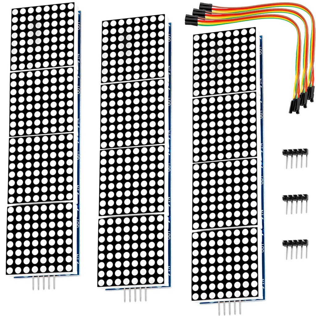
The best things about a LED matrix are the scalability, the variety in size and color, and the wide viewing angle. In this example we use the 32mm 8x8 RED. You can also buy them in green, blue or yellow, but red is the most common and cheapest version. If you have a very limited budget and can wait 2 months, buy them directly from chineese webshops at half the price.
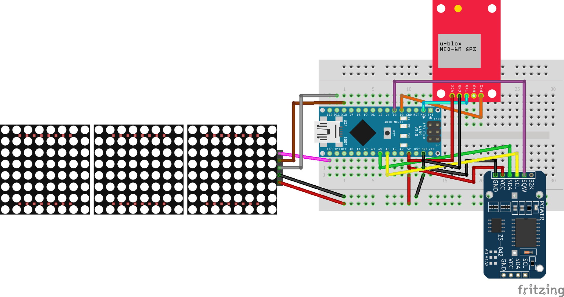
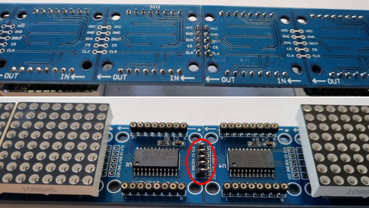
You can buy units with already 4 segments on one PCB, each with its own control chip. If you bend the input connections from 2 units, and solder them to the next one, you get one long matrix with 12 segments. The combination is a 96x8 LED matrix display, that handles like one single board. If you want to reuse the units for other projects or have different hardware, connect them together using wires or jumpers.
Warning: If you connect this 96x8 matrix to the Nano, it will use 1.8A=9W. It gets very hot at some places and may damage your Nano. That is because if it is not controlled, all LED's will light very bright for factory quality testing. To avoid this, use an external power source for your breadboard. Also wire the SPI connections to the Nano before you power the board. Normally it uses about 1W, or 200mA/5V.
Compleet the display wires:
- Connect GND and VCC to the external power.
- Connect the DIN PIN to the Nano D11 PIN, this is the SPI MOSI
- Connect the CS PIN to the Nano D10 PIN, this is the SPI SS
- Connect the CLK PIN to the Nano D13 PIN, this is the SPI SCK
Compleet the Nano power:
- Connect GND and +5V from the Nano to the external power supply.
- disconnect the USB from the Nano, the firmware should already be uploaded in STEP 2.
Be aware that if you want to use examples from the MD_MAX72XX library, it defaults for other hardware. This will result in unreadable pixels on the display.
#define HARDWARE_TYPE MD_MAX72XX::PAROLA_HW
Change the line to this:
#define HARDWARE_TYPE MD_MAX72XX::FC16_HW
This is the default I use in my library.
Test the display:
If connected right, you will see the time/date on the display. This is the same code as used above. Be aware that the input for the display is on the right side.
Step 6: The Basic Clock

For size reference the display and breadboard are on 2 A4 sheets.
Modify the sketch:
Be sure to power the breadboard with the external power first. Now it is safe to plug the Nano USB in your PC.
Jumper testing:
In my final design is use DIP-switches to get some settings during runtime. You can test this with a jumper wire and connect the input PIN to ground.
- D6 'scroll' gets different text lines displayed every few seconds, without animation. add information like ISO week number, temperature etc.
- D7 display brightness for higher intensity.
LED testing:
I also have 2 PINs for LED control. It was easier in my layout to use the analog PINs for digital out. Connect a LED and resistor to GND.
- A6 RTC LED
- A7 Sync LED
Reading distance
For a LED matrix the maximum reading distance = 400 * font height. For our 32 mm display that is 12 meters, if the light conditions and reading angle are perfect.
Step 7: Custom PCB

I designed a custom PCB control board, and have it manufactured without assembly of parts. It uses headers and breakout boards, it is not designed as an integrated production model ;-)
- 5V USB-C power supply.
- oversized condensators.
- backup power supply for 12/24V source.
- LED for PseudoPPS from RTC, should blink in sync with GPS if it has a FIX.
- LED for sync, ON if synched in the last 4 hours.
- double DIP switch, select scrolling and brightness.
- double relay connection, for external 230V control. For safety this relay is placed in an external closed housing.
- connect LED matrix with JST-XH connector.
- RS485 module, control external Nano with 2nd display.
- RJ45 connector for RS485 over UTP, tested with 25 meter UTP cat5.
- BME for temp/humidity/pressure.
- extra I2C connector.
- holes for mounting the display, and holes for mounting housing.
Arduino Remote Control With RS485 Over UTP : 7 Steps - Instructables
In this link the how-to for RS485 remote display.
Step 8: Finished Clock
The display and control board are covered with a top and bottom, made from a wooden plinth. This will protect it from most damage and makes it suitable for hanging or standing. Notice nothing is glued or hot-melted together.
If you are handy create your own or design a 3D-printed housing. It would be nice to see your build.
Compare to other clocks
Now that you have the display project running, it’s time to compare and get some results.
Radio Controlled
In the 1990’s ‘radio controlled’ devices became very popular. In Europe most of them use DCF77, and you probably have a weather station or other device. It should be in sync with our project, if it had good reception in the last few hours.
GPS
If you have a handheld GPS or dashcam, you must let it get a FIX first. But even then, a lot of them are only using the NMEA sentences and are not in sync with our project.
Phone
Network time used by your mobile provider should be accurate. Unfortunately, my phone is usually off 0,5-1,5 seconds.
Website
The website https://time.is is a good example of an accurate clock, it is in sync with our project.
Apps
If you search for 'Atomic', 'NTP' or 'GPS' apps [Android or Apple], you get a lot of hits. Many are however not very accurate, you should delete those from your phone/tablet.
“ClockSync” for Android is a good NTP app and shows the offset.
“Atomic Time” for Android is also a good NTP app. If you turn ‘Milliseconds’ on in the settings it will show you the decimal seconds.
Step 9: 128x8 Version

I made another clock with 4 units, that is a 128x8 matrix. To save some money I ordered the parts directly at the big Chinese web shops. Now they charge the European Tax, so it goes through customs without any problems. The delivery was around 8 days and not 8 weeks I was used to a few year ago.
The matrix was sold as “yellow” but is more light green. The PCB is actually a different design, the width is exactly 32 mm and the LED segments are tight together. You do not see the difference from a distance, but my custom PCB does not fit because it was designed for 32,5 mm width. The difference adds up to 6 mm difference in my original mounting holes. I also had to set the intensity higher than the red one to make it readable. Another difference is that the red LED is casted in clear material, and you can see the actual micro-LED’s, the green ones are casted in milky material making it look like 3 mm LED’s.
The EUR 4,- GPS antenna actually works as good indoors as the one sold in Europe for EUR 15,- Only the cable is half the length, making in better to put in our project casing.
I connected the GPS to the u-center software, where it came up as a ublox 7. The sticker looks almost genuine, but when compared to the original M8N you see the difference. It is also a ROM version without memory, it is not possible to do a firmware upgrade or run it with custom settings. I did a bit of research with Google and found reports of timing mistakes for this model. I placed this clock next to the red one, and initially the timing is 2 seconds off. This it probably a leap-second problem, because the firmware is from 2012. In the past years we had 2 extra leap seconds in 2015 and 2017. When the GPS recieves the new leap-second table from the satellites, the timestamps are good.
Minimal change to the code, to make it work for the bigger display and add the year + week number. Minor change to the font, making the "ij" fit in 4 width.
This verion also runs on the DS3231M [not the SN used in the red version]. They were next to each other for a few days and did the second flip in sync. With cheaper parts it is still 0.1 sec accurate, if you get a FIX every 30 min it is 0.01 sec precise.
Step 10: Budget Clock Version

If you are new to Arduino and have to start from scratch, buy pre-soldered parts. This saves the extra tools needed.
It uses a tiny 128x32 OLED I2C display and the GPS unit in STEP 1.
Step 11: Shutdown Error
Our project runs on a 5V power supply, but internally most components need a minimum of 1,5 to 3 volt. If it drops below this the electronics have a brown out followed by a total shut down. If you have a simple power supply and unplug it you probably do not notice this because it is very fast.
Our GPS has a backup battery to keep some information in memory which helps to get a faster fix in the next few days. The DS3231 RTC has a backup battery that will keep time running for several years. The problem with the RTC is that there is a voltage range where it is high enough to keep current time in memory, but too low to keep counting and thus have a time error. To make it worse, this is in the same voltage range where the backup battery does not take over yet.
In our project I did install a big capacitor that stabilizes the power supply for short hiccups and keeps the display on even when it loses power for about 1 second. But when the power is lost and comes back on you notice a time error somewhere between 0,5 and 5 seconds. The error also depends on the type of ds3231 used, my cheaper "M" version performs better than the "SN" version. On the display there is a "!" to remind you the Arduino has not done a sync with the GPS. It depends on your GPS reception how fast this error is corrected. Keep in mind that the GPS with older firmware is a few seconds wrong until the correct leap seconds information is downloaded from the satellites.
I also ran the clock on a powerbank. Modern high capacity one's for charging your phone cannot be used, they have low current protection. The clock does not draw enough current to switch the powerbank on. An older powerbank with simple circuit and 9 Wh capacity keeps the clock running for about 7 hours. But when the clock is powered on again, the time error was about 5 minutes. The powerbank battery does supply the brown out voltage for a long time before the backup battery takes over.
On professional devices these errors would be minimized in the design, but we just have to accept it when using low budget components.
Step 12: More Accuracy ?
If you need more accuracy, this can only be done with professional hardware, at higher cost. Telecom applications and timeservers use special GNSS timing chips. Those need a fixed antenna position and calibration to millimeter accuracy. The only unknown is time, which then can be solved with only one satellite in view. This makes it possible to have multiple fixes per second. The internal RTC generates timestamps with fractions of milliseconds.
Step 13: Hardware Errors

https://content.u-blox.com/sites/default/files/GPS-WeekNumber-Rollover-Workaround_AppNote_%28UBX-19016936%29.pdf
Depending on your hardware/firmware there is already a compensation build into the GPS unit. This list shows when uBlox recievers will start showing the wrong date. Newer units use new ways to count GPS-weeks, and don not have this problem.


![Tim's Mechanical Spider Leg [LU9685-20CU]](https://content.instructables.com/FFB/5R4I/LVKZ6G6R/FFB5R4ILVKZ6G6R.png?auto=webp&crop=1.2%3A1&frame=1&width=306)


