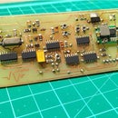
Introduction: 200W Modified Square Wave Inverter With Crystal Control
Hello everyone! Thank you for stopping by this tutorial on how to build a modified square wave inverter that is capable of delivering 200Watts of power.
This inverter delivers a modified square wave AC signal of exactly 50 Hz. This is possible by using a crystal oscillator which helps us to get super accurate frequencies. Other features of this inverter include:
- Waveform shape control and dead time adjustment
- Low Voltage cutoff
- Precise frequency operation without using microcontroller.
The best thing about this design is that it is free from microcontrollers and complex programming and uses traditionally available PWM control chips, counters, frequency dividers and some smart combination of these classic ICs.
So without further adieu let's get started!
** WARNING : This project includes working with high voltage and can give you a lethal shock if you are not careful. Please proceed with these kind of projects only if you have proper electrical knowledge and experience of working with high voltages. Consider yourself warned **
Step 1: Modules/Components Needed
Since this inverter is different from most DIY classical designs available over the internet so I have made the entire project in parts and have eventually combined all of them to make the final product.
Basically the inverter consists of 3 parts:
- DC to DC converter module. It converter the low 12V DC to high voltage till about 300volts. The link to this module, build process details and theory can be found here:
https://www.instructables.com/200Watts-12V-to-220V...
2. DC to AC converter module. It is basically a High voltage H bridge circuit that is capable of converting DC voltage to AC voltage. The link to this module, build process details and theory can be found here:
https://www.instructables.com/220V-DC-to-220V-AC-D..
3. The Modified square wave control module. This is a crystal oscillator controlled TL494 based module that generates the control signals for the MOSFETS of the H bridge. The deadtime and this the waveform can be easily varied using a potentiometer based on requirement. The link to this module, build process details and theory can be found here:
https://www.instructables.com/TL494-Working-With-a...
All these 3 modules come together in this project and make the final intended inverter.
Step 2: The H Bridge
The H bridge essentially converts the DC signal to AC signal, utilizing 4 MOSFETS as switches which turn ON and OFF based on the control signals and generate an alternating signal as output. This topology is very common with controlling motors and their direction.
Here you can see that I have used a small 12V battery to just demonstrate the process and we have a signal which is purely an AC square wave and not the modified square we wish to have. This is because of the SG3525 chip which cannot generate any such signals for a modified output. The SG3525 however features a soft start function which is not there with this TL494 card
Step 3: Making the H-Bridge Module Compatible for Modified Square Wave
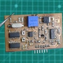
As you can see that the H bridge module was controlled by the very popular PWM control IC SG3525 which was producing square wave of 50Hz which was set by the RC timing components. Now to make this module compatible with the TL494 module (which is in the form of a module/card with header pins), I needed some adapter/breakout board that would be a link to connect both the modules ( H bridge and TL494 card).
Now the square wave output on SG3525 came from pins 11 and 14 which went to the MOSFET driver IC. Luckily I has used an IC socket to make the project instead of directly soldering the IC which made it very very east to completely remove the IC.
So the idea was to just connect the outputs of the TL494 card to the connections where pins 11 and 14 of the SG3525 would initially connect. The power to the TL494 comes from the H bridge module (which is 12Volts).
I gathered a small dot veroboard/ perf board and a couple of male and female headers to make this breakout module. The exact parts include:
- A small piece of perf board
- 1 * 8 male header pins - 2 sets
- 1 * 6 female header pins - 1 set
- 100 ohm current limiting resistors -2
Step 4: Completing the Breakout Board
After about 15 minutes of soldering the breakout board was ready.
One part of the board would fit into the IC socket while the TL494 card would fit on to the female header pin with the connections as described in the previous step.
You can refer to the images to a clear understanding.
Step 5: Observing the Waveform
Now after inserting the TL494 control card to the H bridge module we can clearly see that now instead of just plain and simple we have a modified square wave as the AC output signal.
This works for small test voltages like 12V, now let's ramp it up a few notches!
Step 6: The High Voltage Generator
This is a 200W capable DC to DC converter that converts the 12C from the battery to higher voltages till 300Volts DC. This has an active feedback to stabilize the output voltage and also low voltage cutoff to protect your battery from over discharging. This will be our high voltage source to generate the AC voltage.
Step 7: Testing the Entire Setup
I have now connected the high voltage output of the DC-DC converter to the input of the H bridge and both the modules are powered up with the 12 volts from the battery itself for their internal working. The MOSFETS are responsible for switching the high voltage DC.
I have connected a multimeter to the AC output of the H bridge and as you can see I am getting a stable 200V AC value from this setup. This value can be changed by changing the feedback of the DC to DC converter.
Step 8: Waveform Evaluation
Now since my oscilloscope cannot handle more than 20 volts as input, so I have used a step down transformer (center tapped 12-0-12 volts) to reduce the AC voltage and to evaluate the final AC waveform. As you can see from the images that we are getting the correct waveform at the output.
Step 9: Testing With an Actual AC Load
Okay! so with all the tests done, I was now convinced and confident to finally test this thing with an AC appliance and what better than a small table fan. As you can see I have the complete system set up with the multimeter measuring the AC voltage and the step down transformer system helping me to visualize the waveform when the load would work.
For this setup I have used a 45 watt table fan and a 7.2 AH lead acid battery as the power source for everything.
Step 10: Efficiency Calculation and Conclusion
It was amazing to see that the waveform of my inverter was still a modified square wave despite having an inductive load. The fan worked very nicely with my setup and I operated it for about 10-15 minutes during the test and observed just mild heating of the MOSFETS.
Coming to the efficiency, As you can see in the first image the fan draws about 4.6 Amps from the battery when it is working at full speed. We have used a battery with nominal voltage of 12V.
Here is the calculation:
Input power: 12V * 4.6 A = 55Watts
Output power: 45 Watts (rated power of the Fan)
Efficiency: ( Output/ Input ) * 100 = 83%
Overall I found the efficiency to be about 82% to 84% based upon battery voltage and load which is not half bad considering this is a completely DIY design.
That is all for this article and I hope you learned something in this. Please share your feedbacks and suggestions and I will be happy to answer questions. Also, do watch the video at the beginning to get more information about this build and while you are there consider subscribing to my channel- it surely motivates me to make more projects!
Till then see you in the next one!


