

Introduction: 24-hour World Clock


This World Clock shows the time of day throughout the world. The number ring rotates so the time at any longitude can be seen.
It's marked with time-zones so you can see the official time or just use the longitude to read the solar time.
It uses a 24-hour clock motor or you can modify a normal clock motor to run at half-speed.
Step 1: Map Projection

There are lots of popular (and some weird) map projections available. You can skip this Step if you're not a fan of the maths of map projections.
We need a projection in which the equator is a circle and the continents retain their familiar shapes. So we want the North pole at the centre (or the South if you prefer). We don't want a projection in which the South pole goes off to infinity. We want the North and South hemispheres to be roughly the same radius so that the equator is half way from the centre to the edge. We want the continents not to be cut into pieces. And it would be nice if it fits in a "portrait" or "landscape" picture frame.
If you look through the lists of projections on the web, there isn't such a projection. So I've invented my own. Let's call it the "Curved Star".
The Curved Star is very like the Berghaus star projection but I prefer mine.
In the Berghaus star, there are sharp discontinuities in the lines of longitude and the outer lines of latitude are not circular. Worst of all, Australia is cut into pieces.
In the Curved Star, overland distances from the North pole correspond to the radial distances from the centre of the map. So the lines of latitude are equally spaced. The equator is half way between the centre and the outside.
The Southern hemisphere is divided into six unequal lobes by cuttting along 6 lines of longitude at
- 125° W
- 85° W
- 15° W
- 55° E
- 95° E
- 165° E
The width of each lobe then tapers linearly to zero as you approach the south pole. A linear taper in polar coordinates gives a rather nice curved lobe. (I tried other tapers but linear is simple and looks nice.
You can use the map I have provided or you can make your own. A Windows program to do the projection can be downloaded from GitHub.
Many older world maps you find on the web use Mercator's projection. We all know how Mercator's projection distorts area (so Greenland looks as big as Africa) but it preserves shape and rhumb lines are straight.
The first step is to produce an Azimuthal Cylindrical map. In an Azimuthal Cylindrical map, lines of latitude are equally spaced. So longitude (the x-axis of a Mercator's map) becomes the x-axis of the Azimuthal Cylindrical map. The y-axis of the Azimuthal Cylindrical map corresponds with
R*ln(tan(latitude/2+90))
along the y-axis of the Mercator's map.
Another popular projection is Miller's. The Miller projection is very similar to Mercator's projection but the map is squashed a little as you approach the poles. The y-axis of the Azimuthal Cylindrical map corresponds with
R*ln(tan(latitude*2/5+90))
along the y-axis of a Millers map.
Both Mercator's and Millers maps go to infinity at the poles so both are clipped - usually near latitude 85° North and South.
So now you've got an Azimuthal Cylindrical map. It's a simple matter to turn that into polar coordinates.
radius = 90-latitude
angle = longitude
That gives a Polar Azimuthal Equidistant projection (the one used in the UN logo).
For any point outside the equator, we have to draw it inside a lobe. We find which lobe it's in. LC is the longitude of the centre of the lobe so the tapered angle is
angle = (longitude-LC)*(1-latitude/90)+LC
Finally, we want the part outside the equator to be moved outwards to make room for the number ring. The Southern hemisphere is simply zoomed by a certain percentage.
Step 2: Clock Motor


The number ring rotates once a day. You can buy clock motors that do so on eBay (or you favourite supplier). Search for "clock movement 24 hour". They cost more that standard 12-hour movements but are still a reasonable price.
You will only be using the hour hand so, if possible, cut the minute and second shafts short.
If you don't want to buy a 24-hour movement, you can make your own from a standard clock motor. My Astronomical Clock instructable explains at length how to modify a clock motor so I'll just give a short description here.
You should be able to buy a junk clock for £0.50 in a car-boot sale.
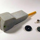
Remove the hands from the motor. Open the motor and take out the gears and the rotor. Extract the coil and the small PCB. The battery contacts should come out as well.
Unsolder the coil wires from the PCB. Unsolder and keep the 32768Hz crystal.
We want to make the clock run at a different speed so we need a circuit that will produce the pulses at the right rate. In this application, the motor should run at half speed so the pulses should be every two seconds. A microprocessor circuit will do the job. We want the microprocessor to run for a year on two AA cells so the current has to be 100uA or less.
I chose a PIC 12F629. I happen to have quite a few of them but any of the small PICs would do instead - they might not even need changes to the code.
The PIC circuit is shown above.
The PIC processor runs using its 4MHz internal oscillator but spends most of its time asleep. Timer1 uses an external oscillator: the 32768Hz we unsoldered crystal from the clock motor. Whenever Timer1 overflows (every 2 seconds), the PIC wakes up and calls an interrupt. The interrupt produces a pulse in the motor coil then returns to the "main program". The main program goes back to sleep.
The total average power consumption when it's driving the clock coil is around 50uA. It needs two AA cells and they'll last a year. Great!
The Timer1 oscillator is "low power" - it drives the crystal with a low current. Clock crystals need a lower current drive than you would normally use on, say, a processor crystal. I tried the PIC circuit with a few 32kHz crystals and they all worked fine with 33pF capacitors.
I've attached the hex and the assembler for the PIC code I used.
I built the PIC circuit on a small piece of stripboard. It fits where the old PCB used to go or you could fit it where the AA cell used to go in the clock motor.
My Astronomical Clock instructable includes an Arduino sketch you could also experiment with but Arduinos are not as good as PICs at very low currents.
Attachments

Step 3: The Map and Number Disk


I clipped the map to an 8x6 aspect ratio which removed some sparsely populated parts of the Pacific and Indian oceans (sorry Kerguelen).
Then I had the map and number disk printed as two 8"x6" photos at a local supermarket. I've attached the Jpegs here. When you download them, they should be 2770x3694 pixels. Check that they haven't been mangled by downloading; if they have been, they're available on Github.
If you'd prefer your own map, use my Windows program to do the projection.
The program allows you to choose a source map and its projection (only Mercator and Miller are currently available). You can specify the overall size of the image (use 500 for testing then 4000 for your final print). You can choose to display the outlines of the lobes, timezones, latitude/longitude and small marks ("Hands") for the centres of the timezones where you read the time.
Your source map should have 180° West and 180° East at its left/right edges and the maximum latitude (North and South) should be the same at the top and bottom of the map. You can use Photoshop or your favourite image editor to clip it to size.
The program always writes its output to tthe file "map.bmp".
I chose a 24-hour clock in the number ring. You might prefer two 12-hour semicircles, one dark for "night" and one light for "day". Once again, use your favourite image editor.
Step 4: Construction


I printed the map as an 8"x6" photo and found an 8"x6" photo frame in a charity shop for £1. 7"x5" frames are easier to find but I thought they were rather small.
Draw a large + on the back of the map so you can line it up later then carefully cut out the space around the equator. Glue the number disk onto thin card to stiffen it then cut carefully around it.
You could glue the map onto the inside of the glass using clear glue such as UHU. I thought it was better to glue stiff "celluloid" from packaging on the back of the map photo to centre the "Northern hemisphere" inside the "Southern hemisphere".
The number disk needs to be fixed onto the hour shaft. You might work out your own way to do it. I used three squares of 1mm polystyrene sheet. I carefully drilled and filed holes in the pieces so they were a tight fit on the shaft (it's tapered) then glued them together. Then I glued the squares onto the back of the number disk while carefully supporting it to ensure it was completely flat. To reduce friction, I glued small pieces of thick card at the edges of the disk to keep the disk slightly away from the back of the map.
The details of how you attach your clock motor will depend on your particular picture frame. I cut a piece of hardboard that could be screwed onto the back of the frame, drilled a hole in it and glued the clock motor and battery holder onto the back.

Second Prize in the
Maps Challenge


