Introduction: 3D Printer Laser Build
I had some 1.5-1.8W high powered lasers I was playing with before I got my 3D printer. It just made sense to find a way to attach the laser to my print head and make an automated laser etcher. Here's how I did it.
Supplies
- M140 A-Type Laser Diode
- 5.6mm TO-18 Laser enclosure: I don't recall where I got mine, but these are available on ebay/Amazon. Depending on what you get, you may need a separate focusing lens.
- Thermal Paste: I had some laying round, but nothing special.
- 12mm Laser Diode Heatsink
- 1.25A Laser Diode Driver
- Safety Fuse
- Schottky Diode for reverse polarity protection
- Buck Converter to step down from 24V
- Connectors:
- Quick disconnects for driver and diode
- JST Connectors for connecting to the control board for pwm
- Wire: I used 18awg security wire from my local Home Depot
Step 1: Assembling the Laser
Start by carefully applying thermal paste to the sides of the laser diode and inserting it into the diode enclosure. Be very careful not to get the paste, which is conductive, on the pins or on the face of the diode. With the diode lightly in place screw on the back of the enclosure carefully, but firmly, to press the diode into place. I made small turns and took the back off to make sure the diode was being pressed in evenly and repeated until it was fully seated. Once installed I soldered on wires, put heat shrink over the pins and wire, pulled the wire out the back of the enclosure, and added a JST SM connector.
With the diode in the enclosure it's time to wire the rest of the circuit. I used JST SM connectors on both input and output of the 1.25A Diode Driver. The input of the Diode Driver gets it's positive leg with a 2A fuse in-line from the Buck Converter and the negative leg from the negative fan pin using a JST HX connector. I installed the reverse polarity protection schottky diode here with the bar towards the controller. The Buck Converter gets its input from the 24V power supply with the output dialed to 8.6V.
Since my Creality 4.2.2 board only had 1 controllable fan port, I cut the part cooling fan wires and used the JST SM connectors to make a connection to the fan ground at the print head. I swapped the connector back and forth between the part cooling fan and the laser. On my SKR 2 board I used the 3rd fan port (FAN2) and have a dedicated connection for the laser.
NOTE: The reverse polarity schottky is not necessary on Creality boards as the fan negative pin connects only to ground through the onboard mosfet. SKR boards have a indicator LED on the fan connector that can leak reverse current to the laser driver while turned off.
Step 2: Laser Mount
To mount the laser on my print head, I modified the Mini Satsana posted on Thingiverse by Kenopy. I left space on the back left for the original, metal BL Touch mount and added a small cup on the side to support the 1.25A laser diode driver from Survivallaser.com. I've attached my remix files here and shared them on Thingiverse.
Step 3: Configuring the Laser
If you're not already familiar please look into compiling your own firmware for your 3D printer using Visual Studio Code (VS Code). It opens up a whole bunch of customization you can take advantage of to really level up your machine. I will not provide config files as my machine is highly customized and it would be very unlikely my config would work for you.
First you'll want to make sure #define FAST_PWM_FAN is enabled is enabled in Configuration.h.
When I first connected my laser to my Creality 4.2.2 board the pwm was very slow, causing the laser to visibly blink, rather than change intensity. I was able to fix this by changing the creality fan pwm PA0 pin from using timer 2 to using timer 5. Thanks to GabrieleMezzera for posting the solution to github. Here are the steps:
- Set {&gpioa, &timer5, &adc1, 0, 1, 0}, /* PA0 */ in /Users/%USERPROFILE%/.platformio/packages/framework-arduinoststm32-maple/STM32F1/variants/generic_stm32f103r/boards.cpp
- Commented #define FAN_SOFT_PWM in Marlin/src/pins/stm32f1/pins_CREALITY_V4.h
- Uncommented #define FAST_PWM_FAN in Marlin/Configuration.h
- Commented #define FAN_SOFT_PWM in Marlin/Configuration.h (DO NOT comment out #define SOFT_PWM_SCALE 0)
- Set #define STEP_TIMER_NUM 4 // for other boards, five is fine. in Marlin/src/HAL/STM32F1/timers.h
I'm not sure if this is necessary for SKR or other boards, but I did not change anything when I switched from the CR4.2.2 to my SKR 2.
For either board, whatever port you use should be configured as a normal fan port, which can then be controlled with the M106 gcode.
Step 4: Bed Tray for Laser Work
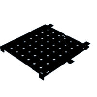
When I first started messing with the laser I just taped stuff (mostly scrap cardboard) to the print bed for testing. Since I've been printing more lately and didn't want to constantly have to scrub tape residue off the print bed I needed a better system to hold things in place.
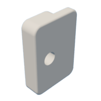
The tray is split in 4 to be printed 1 at a time upside down. The "Guide" pieces then slide in the rectangular slots to make edge stops. My X0 is a little inside these guide slots on the left, so I just made a guide that was a couple mm wider on top to align print media with X0 at the edge guide. There's "feet on the bottom to elevate the tray above my bed clips.
There are varying peg shapes/sizes that fit the 5mm holes on the tray to hold print media in place. All of these should be printed with the top side down to avoid any need for support.
I've attached the STL files here and on Thingiverse.
Attachments
Step 5: Generating Gcode
Whatever method you use to generate your laser gcode you'll want to make sure that the hotend fan is on when using your laser. This helps cool the laser and extend its life. For the Creality boards this is not an issue, since the hotend fan is always on with power to the control board. On the SKR 2 there are a couple options.
- Configure the hotend fan as a regular fan and add Custom Gcode commands to your start/stop gcode. This is what I have set up now with my hotend fan plugged into the FAN1 port. I add M106 P1 S255 to my start code and M106 P1 S0 to my end code.
- Configure the hotend fan as a controller fan. This will automatically turn the fan on when the stepper motors start moving and turn it off after the printer is stationary for a set period of time. Configuring this way still allows for manual control using the M710 command.
There are several programs to generate laser etching/cutting gcode.
- Laserweb
- Laserweb is a pretty impressive free tool. It packs a lot of features, but is not the most intuitive to use. It also feels a little resource intensive and my little 10 year old, convertible PC has a bit of a hard time keeping up. I'm sure if I put more time into becoming familiar with this software it would be adequate for 80-90% of the stuff I would do with my laser.
- Image2Gcode
- Image2Gcode is perfect for simple, monotone black and white jobs. Great for outlines or say burning off a solder/pcb etch mask. It is capable of doing raster images, but I haven't received the cleanest results with this program.
- CrealityWorkshop
- Creality Workshop has a very simple interface. For very simple trace/outlines it's fine. I really can't recommend it for anything complex like raster images.
- LaserGRBL
- I can't really give much feedback on LaserGRBL. It's really designed for a GRBL machine instead of a Marlin Gcode machine. I tried it early on, but the only way to get usable gcode out of it was to manually edit the gcode it produces to work with marlin ie: replacing all M3 commands with M106.
- LightBurn
- Lightburn appears to be the best option out there, but it is not free. At the time of writing this it's a one time fee of $60. If you plan on doing anything other than monotone black and white then it may be worth it. There is a trial period and from what I've seen the software is well written and very intuitive and easy to use.


