7 Segment Display Array

10K14839

Intro: 7 Segment Display Array

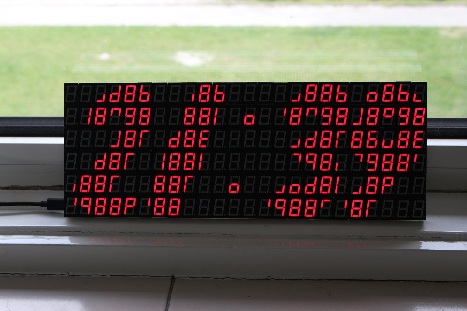
I've build an led display made out of 144 7 segment displays controlled by an arduino nano. The segments are controlled by 18 MAX7219 ic's which can control up to 64 individual leds or 8 7 segment displays. The array has 144 displays made each up of 8 individual leds so the array has an total off 1152 leds you can control.

STEP 1: Get Your Components

1 x Arduino Nano

1 x PCB

144 x Common Cathode 7 segment 1 digit displays

18 x MAX7219

18 x 10uf Capacitor (0603)

18 x 100nf Capacitor (0603)

19 x 12k Resistor (0603)

1 x Female Micro usb

42 x Female header

1 x Tiny RTC (optional)

1 x 2A Powersupply

STEP 2: Order Your PCB

Here you can download the Gerber files for the PCB of the display. Upload them through https://jlcpcb.com/quote#/ or a different manufacturer to order them.

STEP 3: Solder the Components

Solder all the components on to the PCB as shown in the schematics. If u have little or no experience in SMD soldering I suggest u watch this tutorial on SMD soldering first.

If u are going to use the display as a clock solder the headers of the Tiny RTC on de side of the battery.

STEP 4: Display As a Clock

When you finished soldering all the components download the code and upload it to the arduino before putting it into the display. If u want to display something custom have a look at Step 5.

STEP 5: Make Custom Code

If u want to show something custom you need to code it by by hand. In the example code different segements aka pixels are shown in bytes with each bit one segment: 0bDP-A-B-C-D-E-F-G e.g. 0b01011011 will show a 5.

The example code has 3 different ways to show pixels. The first way is to use the putPixel(x, y, byte); function to replace one pixel of the display at the location x, y (0, 0 is top left 5, 23 is bottom right).

The second way is to use the addPixel(x, y, byte); function it works almost the same as the putPixel() function but instead of replacing the pixel it adds the pixel to the original one.

The last way is to use the fillPixel(x1, y1, x2, y2, byte); funtion to fill a rectangle from x1,y1 to x2,y2 with the same pixels.

STEP 6: You're Done!

Congratulations you're done! Now you can program the display the way you like it. And if u made the display dont forget to share it :)

30 Comments

Help me out a bit... I'm trying to determine on which usb micro connector to use.... thanks!

I'm about to solder up the display onto the boards.
Here's an updated version of the code that will work with the 7 button switch shield we designed for the clock. We've added time/date mode, brighter/year up, dimmer/year down, hour/month up, hour month down, minute/day up, and minute/day down. Changing the minute sets the seconds to 0.

Message me if you are interested obtaining a board.
This is an awesome addition. This 7 seg clock concept is a work of art.
Many thanks to my friend Octavian, this code fixes a problem we had with the display where some of the MAX7219 would get stuck and show all 8s or all blank. The MAX 7219 is basically reinitialized every cycle. Eliminated the blinking colons and added seconds at the top center of the display.

I've noticed that after about 3 days I get a funny thing happen on my display. There's a pocket of all blank digits or a pocket of all 8s. Seems to happen most often in the fourth row but I've seen it in other locations. Sometimes it's stretched across the whole row. I'm guessing it's a memory glitch in my Nano clone. As soon as I hit reset, it goes away for another 3 days or so.

Anyone else see something like this on their display?
If I'm not wrong, the current you set is 5V/12k*100 = 40mA per segment. This means that, assuming 50% of segments are light up, the current consumption is roughly 20A (100W at 5V). Which seems a bit too much for me. So.. what is the actual current consumption of the display?
I noticed that the intensity in SW is set to 3 (i.e. 7/32), which means that the total current consumption is roughly 4A, assuming about half of them are light in some time. Less than 100W, but still a lot...
I think you're missing that the MAX7219 is scanning the 8 digits it controls at 800Hz. It's not actually turning all the segments on at the same time. I have a test program that turns all 144 digits to the number 8 and it doesn't even top 2A.
Ah, nevermind! Noticed my RTC was a DS1307 and changed the reference and a function call and all is well now!
Assembled my clock over the holiday. Test mode works fine. Pac Man looks fine. Clock stuck at 1:00. Which RTC lib did you use? Not sure which one to choose, my RTC is not updating.
Got my boards in one week! That's pretty awesome! Other parts are rolling in...

Looking forward to putting this together.
One other question, what is the size of the PCB? I'm trying to measure it and it looks like it is about 305mm x 117mm.

Thanks!
Close, its 305mm x 114mm
You have provided a brilliant idea for using old 7-segment display's which we may have stocked up. Wonder if is possible to make a smaller version?
I used 0.28" 7 Segment displays on my build making it only quarter of the size. It then becomes a desktop alarm clock.
I Love this ! Thanks for sharing
More Comments