Introduction: 7-segment to Display ADC #Arduino Values, #Arduino


In this article I will make a project that is still related to the previous article. Namely processing ADC data.
so you don't need a serial monitor to see the value of the adc data. in this article I will make an ADC Value viewer display. so you don't need a serial monitor to see the value of the adc data. in this article I will make an ADC Value viewer display.
You can read the article below to find out how to use the "7-Segment" Module
Step 1: Required Components


Components needed for this article:
- MAX7219 7-Segment Module
- Arduino Nano
- wire Jumper
- USB mini
- Potentiometer
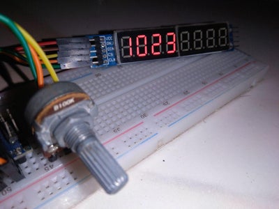
Step 2: Assemble Components


See the schematic above to assemble the components correctly.
Aeduino to Component
+5V ==> 3.Potentiometer & VCC
GND ==> 1.Potentometer & GND
A0 ==> 2.Potensio
D12 ==> Data IN
D11 ==> CLK
D10 ==> CS
Step 3: Programming
Copy and paste the code below:
#include "LedControl.h"
LedControl lc=LedControl(12,11,10,1);
void setup() { Serial.begin(9600); lc.shutdown(0,false); lc.setIntensity(0,8); lc.clearDisplay(0); }
void loop() {
int adc = analogRead(A0);
lc.setDigit(0,7,adc/1000,false); lc.setDigit(0,6,(adc/100)%10,false); lc.setDigit(0,5,(adc/10)%10,false); lc.setDigit(0,4,adc%10,false);
Serial.println(adc); delay(100); }
Original files can be downloaded below:
Attachments

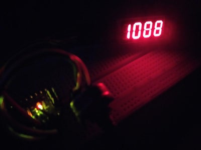
Step 4: Result
for the results can be seen in the video above.
when the potentiometer is rotated to the right, the value will be even greater and mentik in 1023)
when the potentiometer is moved to the left, the value will be greater and mentik at 1023)


