Introduction: ARDUINO LCD CUSTOM ICONS


Did you ever wonder how you can generate your own icons or characters on one of the LCDs
In this instructable, I will provide examples for a house, thermometer and humidity sensor. Animations for a rain storm and cup anemometer is also included. Others may follow. I used tinkercad.com to simulate the circuit since I only have 3.3 volt (Power and Logic) LCD screens (suitable for raspberry pi's and ESP32's) and not the 5 volt ones for arduinos. Tinkercad circuits is very useful. If you want to generate your own circuits and LCD icons, you do not need an Arduino on hand.
Skills required:
Understanding of circuits
Arduino Programming
Supplies
Arduino Uno or some other Arduino
LCD 16x2 or 20x4. Make sure it is for 5 volt Power and Logic (some is 3.3 volt). Most LCD's use the HD44780 controller and will be compatible with this code
Lots of Male to Male jumpers
Breadboard
Potentiometer (Try anything from 5 KOhms-250KOhms). 5 KOhms work well in Tinkercad. Most resources use 250 KOhms
220 Ohms resistor
Step 1: BUILD YOUR CIRCUIT AND LOAD SKETCH
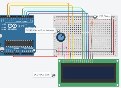

Build your circuit exactly as in the image. Make sure the Arduino and LCD is not powered.
Load a Arduino Sketch attach (There is a vew). You may study the sketch to understand how it works. Valuable info can be found on https://www.engineersgarage.com/arduino/making-cus...
Basically each each block in the 16x2 matrics have a sub matrics of 8x5 dots or bits. each of this bits need to be switched on or of.
My sketches use 4 of these blocks to create one icon
For the above image the code will be
byte dots[8]={B00000, B00000, B01010, B00000, B10001, B01110, B00000, B00000}

Step 2: RUN YOUR CIRCUIT
If you want more detail on how the LCD works (Memory etc), the following resource is very useful
https://www.engineersgarage.com/arduino/making-cus...
The Circuit and sketch is public on Tinkercad. You can experiment with it
https://www.tinkercad.com/things/g6IFAg6ayAL-lcd-16x2weathericons-v2/editel
The following page https://maxpromer.github.io/LCD-Character-Creator/ may assist you in designing your characters
You can also run this with an ESP32 (I tested it on a WEMOS LoLin32). You may have to change your pinout to suite your ESP and the initialization line in the sketch
My ESP32 Pinout is attached in the word document. Remember to use a 3.3v LCD for ESP32 (5v LCD is for ARDUINO)


