Introduction: Adjustable Voltage DC Power Supply Using LM317 Voltage Regulator


In this project, I have designed a simple adjustable voltage DC power supply using the LM317 IC with an LM317 power supply circuit diagram. As this circuit has an inbuilt bridge rectifier so we can directly connect 220V/110V AC supply at the input. The circuit converts 230volt / 110volt AC to 0-12volt DC.
You can also monitor the output voltage on the digital voltmeter, mounted on the PCB. This circuit can be used as a variable DC power source for different electronics projects.
Step 1: Components Required:

Step 2: LM317 Voltage Regulator
Before working with the LM317 regulator we should know the pros and corns of the LM317 regulator.
So in this video, I have discussed the following topic of LM317 which gives you a clear idea about LM317
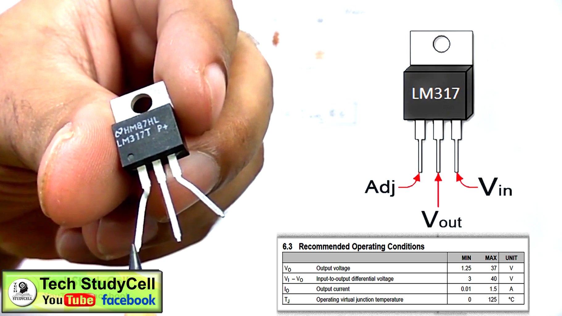
1. Operating Condition of LM317 from Datasheet [voltage, current, temperature rating, etc]
2. Explained how the LM317t circuit works with voltage equation [ use of capacitors, resistors in circuit]
3. Pinout of LM317t ic [Adjust pin, output pin & input pin]
4. How to make variable dc power supply circuit with LM317t on a breadboard
5. LM 317 circuit analysis [ input and output voltage measurement with multimeter]
6. How to use LM317 as a fixed voltage regulator [LM317t as 7806]
7. How to calculate power dissipation in LM 317 [ When heat sink should be used with LM 317]
8. Protections for LM 317 circuit for different applications from LM317 datasheet
I have discussed all the features of the LM317 Adjustable Voltage Regulator with different Practical Experiments, like motor speed controller, LED dimmer, variable DC power supply, etc.
Step 3: LM317 DC Power Supply Circuit:

You can refer to the circuit diagram for the LM317 variable DC power supply. I have mentioned all the component's rating in the circuit.
First, the step-down transformer reduces the voltage 220V/110V to 15 volt AC.
Then a bridge rectifier converts 15V AC to 15V DC.
At the input of the LM317 IC, the voltage is 15Volt to get the maximum 12V DC at the output.
The output voltage can be controlled by the potentiometer.
Step 4: Testing the Circuit on Breadboard

Before the PCB design, I have tested the circuit on the breadboard.
For this circuit the maximum current limit for the circuit is 1.5Amp and the maximum output Voltage is 12Volt.
As the LM317 is a linear voltage regulator, so input voltage will be always greater than the output voltage. If the difference between input and output voltage increases the efficiency of the circuit decrease.
Step 5: PCB for LM317 Power Supply Circuit

After testing on Breadboard I have designed the PCB for LM317 DC Power Supply so that I can use the circuit as a power source for my different electronics projects.
To get the PCB for LM317 power supply, you can follow the following steps:
1. Download the Garber file from the following link:
https://drive.google.com/uc?export=download&id=1B-8pcPcWL284UoGl3vN1fB1sgFlqQ336
Step 6: Order the PCB

After downloading the Garber file you can easily order the PCB at $2 only
1. Visit https://jlcpcb.com and Sign in / Sign up
2. Click on the QUOTE NOW button. Home
Step 7: Uploading the Gerber File and Set the Parameters


3. Click on the "Add your gerber file" button. Then browse and select the Gerber file you have downloaded. Also set the required parameter like quantity, PCB color, etc
4. After selecting all the Parameters for PCB click on SAVE TO CART button.
Step 8: Select Shipping Address and Payment Mode


5. Type the Shipping Address.
6. Select the Shipping Method suitable for you.
7. Submit the order and proceed for the payment.
You can also track your order from the JLCPCB.com
My PCBs took 2 days to get manufactured and arrived within a week using the DHL delivery option. PCBs were well packed and the quality was really good at this affordable price.
Step 9: Solder the Components on the PCB


Solder all the components as marked on PCB. Fitted the step-down transformer and connect the primary and secondary as mentioned on PCB.
Connect the 220 volt or 110 volts at the input of the circuit.
Always take proper precautions while working with high voltage (110V or 220V).
Step 10: Finally !!


Our LM317 Adjustable power supply is ready. Now we can connect any small DC load like LEDs, DC motors, etc at the output.
The maximum current limit for the circuit is 1.5Amp and the Maximum output Voltage is 12Volt.
Thank you for your time. Please share your feedback and also let me know if you have any queries regarding this project.


