Introduction: Architecture in the Making: Studio H2O Facade Prototype


Designers: Adika Djojosugito and Martinus Setiawan
This project is the product of an architecture design studio taught by Adam Marcus (Variable Projects) and Margaret Ikeda & Evan Jones (ASSEMBLY) at California College of the Arts Division of Architecture in spring, 2014. The studio, titled "Architecture In The Making," explored pragmatic opportunities for leveraging digital fabrication technologies in the design and construction of highly performative building facades. While developing proposals for a new building for REALM Charter School in Berkeley, California, the studio collaborated with the Autodesk / Instructables Pier 9 Workshop in San Francisco to produce a series of full-scale building envelope prototypes. Fabricated from 18 ga. steel, these prototypes allowed the students to work at 1:1 scale and to develop a comprehensive understanding of performance, detailing, and assembly. (See this link for more information on the studio.)
This project, Studio H20, was designed by students Adika Djojosugito and Martinus Setiawan. It builds upon a one-week design exercise in which students designed a small farm stand structure in rural California. The purpose of the exercise was to explore how a building enclosure could be designed to address multiple functional requirements. (See this link for Adika & Martin's Instructable for their farm stand project.)
Step 1: Building Design


The focus of the Studio H20 project is water conservation, both as a design driver for the building proposal and also as a curricular component for REALM Charter School's "Studio H" design-build program. The geometry of the building responds to the parallel and diagonal urban grids of Berkeley, and the program is organized according to two aspects of the school's curriculum: Studio H, the school's design-build program, and Studio H2O, a new program that is focused on hydroponic agriculture as an educational tool. The project includes an aeroponic farming system, which allows for a more efficient use of water (using less than 1/8 of the water consumption of land cultivation). The proposal also includes a grey water system that will integrate water collection from surrounding rooftops, and allowing the building to harvest enough water throughout the year to withstand several rainless months.
Step 2: Facade Design


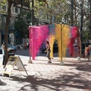
The building envelope system is a custom perforated steel screen that modulates light, shading, and privacy according to the interior programs and their solar and street exposures. The density and size of perforations change locally according to these programmatic requirements, and the global pattern is driven by a water graphic that is inspired by the project’s focus.
The panels are fabricated from 18 gauge stainless steel, and bent to incorporate flanges for attachment on the top and bottom edges. The facade system also doubles as a roof guardrail at the top of the building.
Step 3: Fabrication Process


Three prototypes were produced in the development of the facade system. Each of these prototypes was fabricated on the Omax waterjet at the Pier 9 Workshop in San Francisco. The process for each prototype included the following steps:
- Modeling of the parts in 3D software.
- Flattening / unrolling 3D geometry into a 2D line drawing.
- Export drawing as a DXF file.
- Complete toolpathing in the Omax Layout pathing software. Important considerations for these prototypes included making sure that the water jet (which has a thickness to it) was directed along the correct side of each cut line.
- Fabricate the parts using the Omax Make software.
The most important aspect of this project that needed refinement through the prototype phase was the geometry and quantity of perforations. The initial prototype, which included nearly 2000 holes, some as small as 1/4", took nearly an hour to cut—much too long to suggest that system would be feasible when scaled up. The final prototype increased the size & spacing of the holes to reduce the cut time by nearly 70% while maintaining the gradating quality of the overall pattern.
Step 4: Assembly Process


The prototypes were all assembled at CCA's shop. The bends in the panels were made using a press break. Small cuts/notches were cut with the waterjet to index the precise location for each break, so that the students knew exactly where to line up the break. Standard steel unistrut framing was used for backup structure.
The assembly drawing above documents the assembly process both for the prototype and for a speculative installation on a building facade.
Step 5: Final Prototype


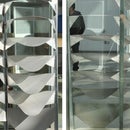
The final prototype measures 45"w x 54"h and was presented at the studio's final review on May 3, 2014 at CCA.


