

Introduction: Arduino FFT Audio Spectrum Analyzer on 8x32 Color Matrix WS2812B
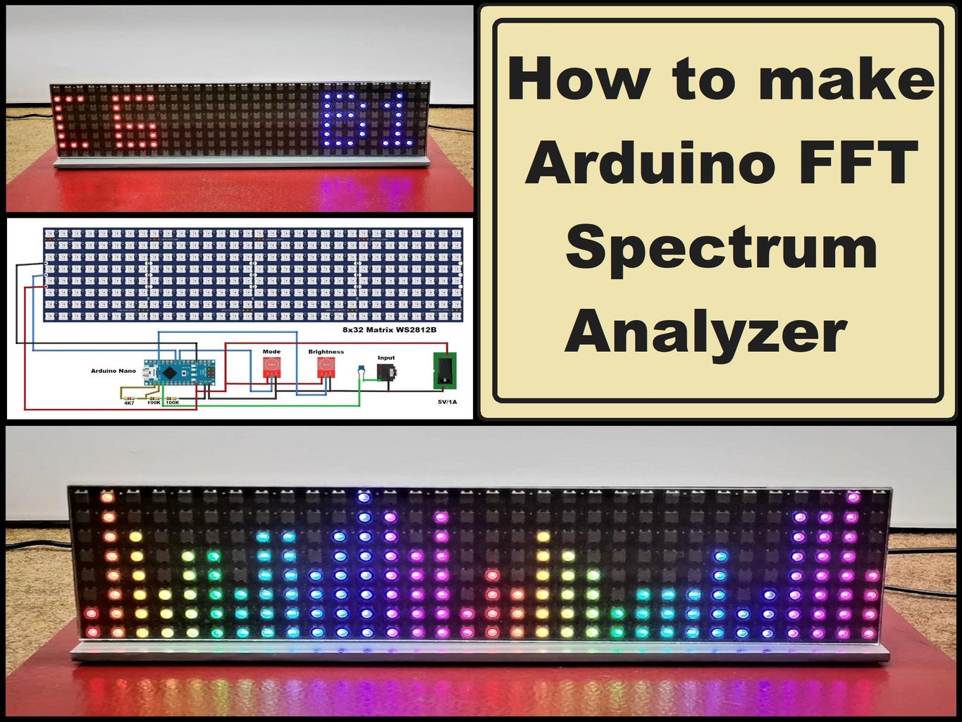


This is an extremely simple, but still visually very effective project, and can serve as a gadget on your desktop, or as an addition to an audio device.
Supplies

- Arduino Nano R3
- 8x32 matrix WS2812B
- pushbutton or capacitive touch switch x 2
- Capacitor 100 nF
- Resistor 100k ohm x 2
- Resistor 4.75k ohm
Step 1: Description
The spectrum analyzer displays the amplitude of signals as a function of frequency, allowing engineers and technicians to visualize and analyze signal characteristics. In particular, the audio analyzer performs a visual presentation of an acoustic signal in the frequency domain, where the frequency of the signal is displayed on the x-axis, while the amplitude of a certain frequency is displayed on the y-axis. In several of my previous videos I have presented several different types of such devices, but this time the FHT Arduino library is used for the first time. This library is several times faster than the commonly used FFT library, but at the expense of speed certain loss of resolution and precision appear at the two ends of the audio range.
However, in the specific case we do not have to develop a measuring instrument but a simple gadget, we do not need extreme precision, we just have to turn on a handful of LEDs in musical rhythm.
By the way, the project has been submitted to the Arduino Project Hub by the user with the nickname januks and is actually a rework of Shaajeb's excellent Spectrum analajzer project. I made minimal modifications to the hardware and code based on my ideas and requirements.
Step 2: Parts

This project is sponsored by PCBWay. They has all the services you need to create your project at the best price, whether is a scool project, or complex professional project. On PCBWay you can share your experiences, or get inspiration for your next project. They also provide completed Surface mount SMT PCB assemblY service at a best price, and ISO9001 quality control. Visit pcbway.com for more services
The device is really simple to build, and consists of only a few components:
- Arduino Nano MCU board,
- 8x64 color Led Matrix with WS2812B adressable leds
- Two (three) touch buttons
- three resistors
- and one capacitor
Step 3: Demonstration

Now let's see how the device works in real conditions
Considering that it is very simple, the device works immediately without any previous settings. One button is used to adjust the LED light intensity in 7 steps. With the other button we move through 6 different mods with specific color sets, and we can also add more, with very small modifications to the code.
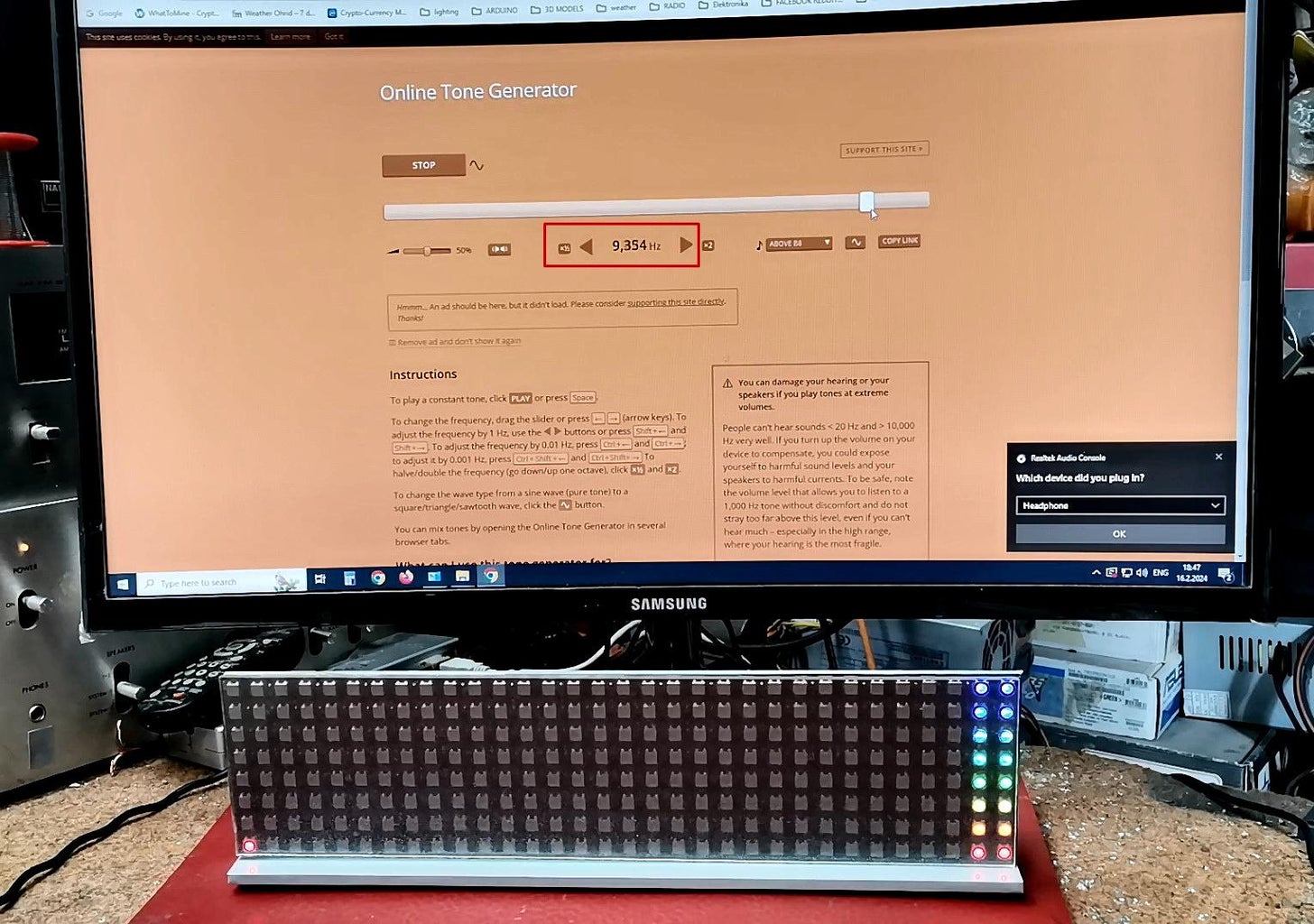
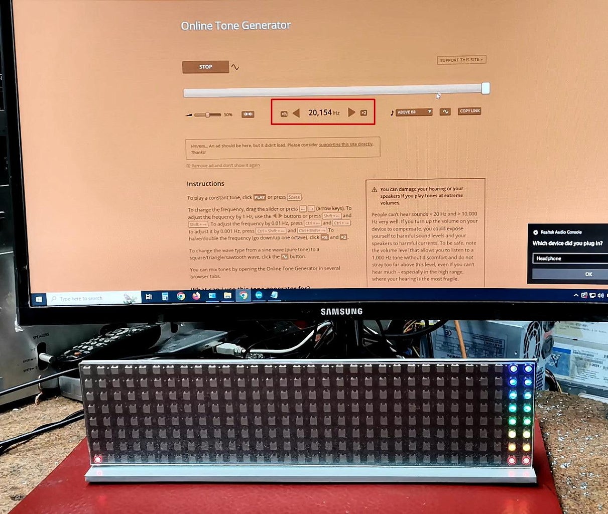
Next, let's test the frequency range that this analyzer covers. For this purpose we will use a simple online tone generator. As you can see, the device covers the entire hearing range, from 20 Hertz to 20 kilohertz. Such a large-range device is excellent when is used for visual FFT analysis, but has one practical drawback when it comes to presenting musical materials.
Namely, a large percentage (perhaps 90%) of this music signal is in the range up to 10Khz, and only a small part belongs to higher frequencies. This would practically mean that for the entire time that the music signal is being emitted, the far right part of the analyzer would be inactive. Let's see how it looks in practice (Here is an example with a speech signal, so we will try it with musical material as well). Since, as I mentioned at the beginning, this is a visual decorative addition, and not a precise measuring instrument, it is desirable to reduce the bandwidth by half, actually to 10 Kilohertz.
For this case I made some modification in the code, but it is also desirable to set a simple Low-pass filter on the input. Let's test the range with an online tone generator at the input. The range is up to 10Khz
Now, in this case the matrix is completely filled and visually it looks much better.
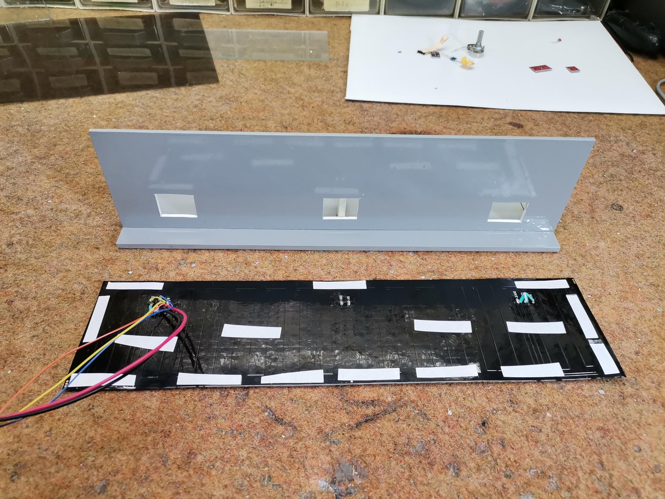
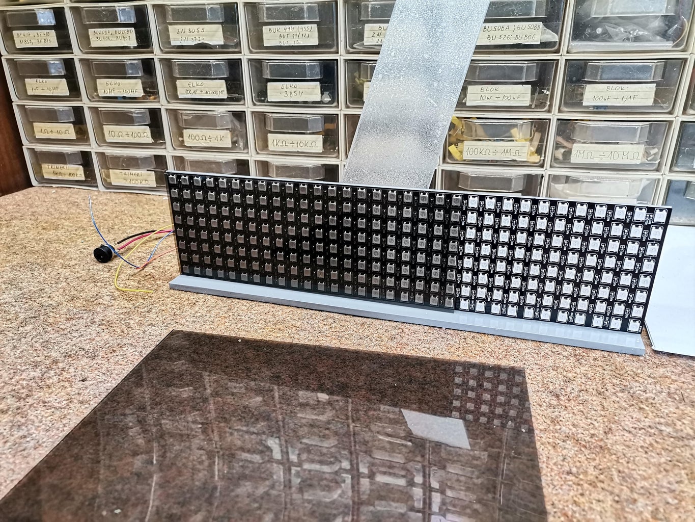
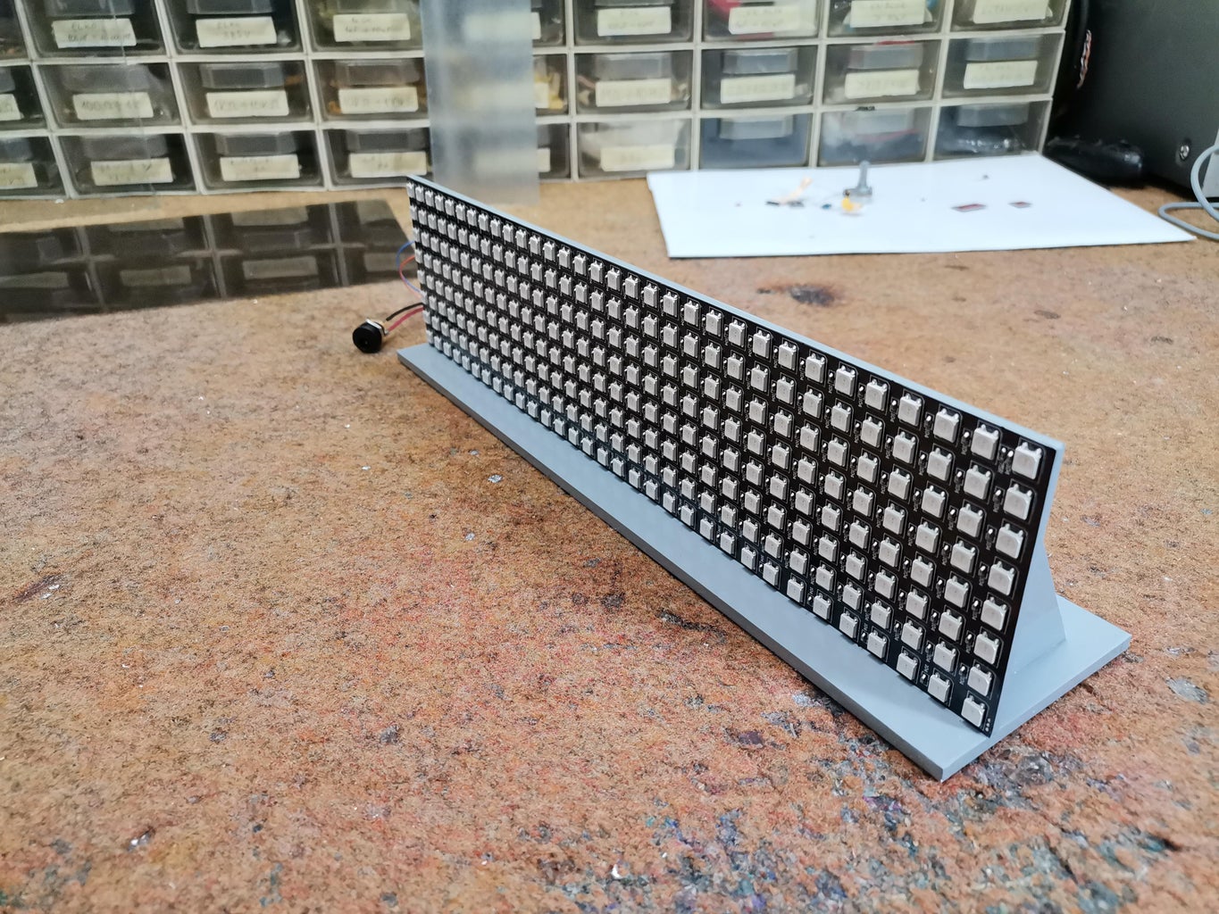
As for the external appearance of the device, I tried to make a simple, but still functional version made of PVC board and glass with a thickness of 4 mm.
Step 4: Conclusion, Schematic,code

And finally a short conclusion.
This is an extremely simple project intended for beginners, but still visually very effective and can serve as a gadget on your desktop, or as an addition to an audio device. It can also be used as a simple school FFT spectrum analyzer instrument intended for educational purposes


