Introduction: Arduino Metronome
When learning a new musical instrument as a kid, there are so many new things to keep focus on. Keeping pace in the right tempo is one of them. Not finding a functionally complete and convenient metronome meant the best excuse to start building again with my kids. In this Instructables post you'll find the functional description, parts list with webshop links and prices, wiring diagram for assembly, and complete Arduino source code.
Step 1: Functional Description
It would be nice to have a metronome device with the following functions to use it at home or at the music school conveniently.
- Compact form factor to fit small places on top or next to musical instruments,
- Battery operated, robust and portable to carry around,
- Easily set up even for kids, BPM value always displayed,
- Adjustable beats per minute with a Rotary knob, up to 240 BPM
- Audible tact with volume control,
- Silent mode for overnight headphone practice,
- Visual feedback of beats (1/4, 2/4, 3/3, 4/4, 6/8, etc.) up to 8 LEDs,
- With or without leading accent, with visual and audible feedback.
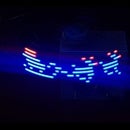
Switching on, metronome mode will start at 60 BPM showing on the small display and letting the pace be tuned by the rotary knob between 10 and 240. Neopixels show the beat in blue LEDs while the buzzer ticks. Pressing the knob will switch to beat adjustment mode and green LEDs will indicate the set beat structure. Rotary knob will increment or decrement the beat structure (2/2, 3/3, 4/4, 6/8, etc.). Above 8 LEDs, further rotating clockwise, leading accent will be turned on, and the first LED will indicate this in red. Leading accent will have audible feedback as well. It can be turned off by rotating counter-clockwise. Pressing the knob will switch back from beat adjustment mode to metronome mode.
Step 2: Parts List
You will need a case. Any shape or size can be bought, but we had a nice black metal case of an old manual VGA switch disposed of a friend. The rest of the parts are listed below.
- 9V Battery, USD 1.50
- Battery connector cable, USD 0,16
- Arduino Nano with pin headers, USD 2.05
- Nano IO Extension Shield, USD 1,05
- Mini slide switch for power, USD 0.15
- Piezo buzzer, USD 0,86
- Adafruit Neopixel WS2812 8-bit, USD 1,01
- OLED Display 128x64, USD 1,53
- Rotary encoder, USD 0,50
- Dupont cables F/F, USD 0,49
Total price of the components are less than USD 10,-
Step 3: Wiring Diagram
Use the Nano IO Extension Board so as not to bother with soldering multiple GND and VCC connections. Minimal soldering will be needed for the Nano pin headers and for the Neopixel module connectors. Using Dupont wires allows stable connections for the rest of the wiring as shown on the diagram. The 9V battery is connected to GND and VIN, the latter through the power slider switch. The rotary encoder module has an integrated switch button, that is shown separately in the diagram for easier understanding of how to connect them. Rotary part (CLK and DT) is connected to PIN2 and PIN3 respectively, because these are the only NANO pins capable of Interrupt handling. Rotary GND is connected to Nano's GND PIN of course. The integrated switch button is connected to PIN4. Piezo buzzer is connected to PIN5 and GND. Adafruit Neopixel module is connected to PIN7 and its VIN and GND to Nano's 5V and GND respectively. Small OLED display is connected to the I2C bus interface, which is PIN A4 and A5 for SDA and SDL. VCC and GND goes to Nano's 5V and GND of course. That concludes our Dupont wiring.
Step 4: Arduino Source Code
The code below is incomplete because Instructables rips tags to prevent injection attacks for security reasons.
Feel free to ask the code in the comment section providing your email address.


// Metronome, Leading Accent, Visual&Audible Tact - 2019 Peter Csurgay
#include
#include
#include
#include
#include "TimerOne.h"
#define SCREEN_WIDTH 128
#define SCREEN_HEIGHT 64
#define OLED_RESET -1 // Reset pin # (or -1 if sharing Arduino reset pin)
Adafruit_SSD1306 display(SCREEN_WIDTH, SCREEN_HEIGHT, &Wire, OLED_RESET);
#define pin_neopixel 7
#define NUMPIXELS 8
#define BRIGHTNESS 32
Adafruit_NeoPixel pixels = Adafruit_NeoPixel(NUMPIXELS, pin_neopixel, NEO_GRB + NEO_KHZ800);
#define IDLE_11 0
#define SCLK_01 1
#define SCLK_00 2
#define SCLK_10 3
#define SDT_10 4
#define SDT_00 5
#define SDT_01 6
int state = IDLE_11;
#define CLK 2
#define DT 3
#define pin_switch 4
#define pin_buzzer 5
int bpm = 60;
int bpmFirst = 0; // LED On at First, Off at the rest...
int tack = 4;
bool leadingTack = false;
int pos = 0;
int curVal = 0;
int prevVal = 0;

void setup() {
  pixels.begin();
  pinMode(pin_buzzer, OUTPUT);
  Timer1.initialize(1000000*60/bpm/2);
  Timer1.attachInterrupt(buzztick);
  pinMode(CLK, INPUT_PULLUP);
  pinMode(DT, INPUT_PULLUP);
  pinMode(pin_switch, INPUT_PULLUP);
  attachInterrupt(digitalPinToInterrupt(CLK), rotaryCLK, CHANGE);
  attachInterrupt(digitalPinToInterrupt(DT), rotaryDT, CHANGE);
  if(!display.begin(SSD1306_SWITCHCAPVCC, 0x3C)) { // Address 0x3D for 128x64
    for(;;); // Don't proceed, loop forever
  }
  display.clearDisplay();
  display.display();
}

void loop() {
  if (digitalRead(pin_switch)==LOW) {
    delay(100);
    while(digitalRead(pin_switch)==LOW) ;
    delay(100);
    Timer1.detachInterrupt();
    showGreenTacks();
    while(digitalRead(pin_switch)==HIGH) {
      if (curVal>prevVal) {
        tack+=1; if (tack>8) { if (leadingTack) tack = 8; else { leadingTack = true; tack = 1; } }
      } else if (curValprevVal) {
    bpm+=2; if (bpm>240) bpm = 240;
  } else if (curVal=100) display.print("       "); else display.print("        ");
  display.print(bpm);
  display.display();
}

void buzztick() {
  if (bpmFirst==0) {
    int volume = 4; if (leadingTack && pos==0) volume = 8;
    for (int i=0; i
Participated in the
Arduino Contest 2019


